





 asdar.id menyediakan Member Premium Download untuk download file tanpa embel-embel iklan dan halaman, apa lagi harus menunggu timer yang begitu lama. Dengan berlangganan Member Premium Download, semua file dapat didownload dengan singkat langsung menuju ke sumbernya!, klik DISINI untuk DAFTAR atau DISINI untuk LOGIN :-) Jika ada pertanyaan silahkan hubungi Admin DISINI. Untuk cara download file Member Free Download, bisa membaca Tutorial Download yang ada dibawah Timer (halaman Safelink) saat menekan tombol download.
Chilled water systems are widely used in commercial buildings, office complexes, hotels, hospitals, industrial facilities, and other large-scale projects that require efficient air conditioning. Properly designed chilled water piping networks help distribute chilled water between the chiller plant and air handling units (AHUs) to maintain comfortable indoor temperatures and support reliable HVAC operation.
For civil engineers, mechanical engineers, HVAC designers, contractors, and AutoCAD drafters, Chilled Water System Details DWG AutoCAD to explore a technical drawing reference for understanding equipment arrangements, piping connections, riser configurations, and chilled water distribution components.
Definition of Chilled Water System Details
Chilled water system details are technical drawings that illustrate the arrangement and connections of equipment and piping used in a chilled water cooling system. This system generally consists of chillers, chilled water pumps, supply and return pipes, control valves, isolation valves, and air handling units that transfer cooling throughout a building. The chilled water is circulated from the chiller to the cooling equipment, where it absorbs heat from the building’s air before returning to the chiller for cooling.
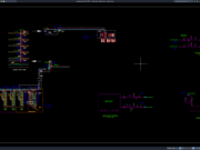
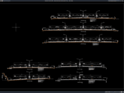
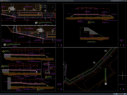
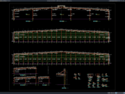
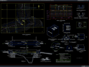
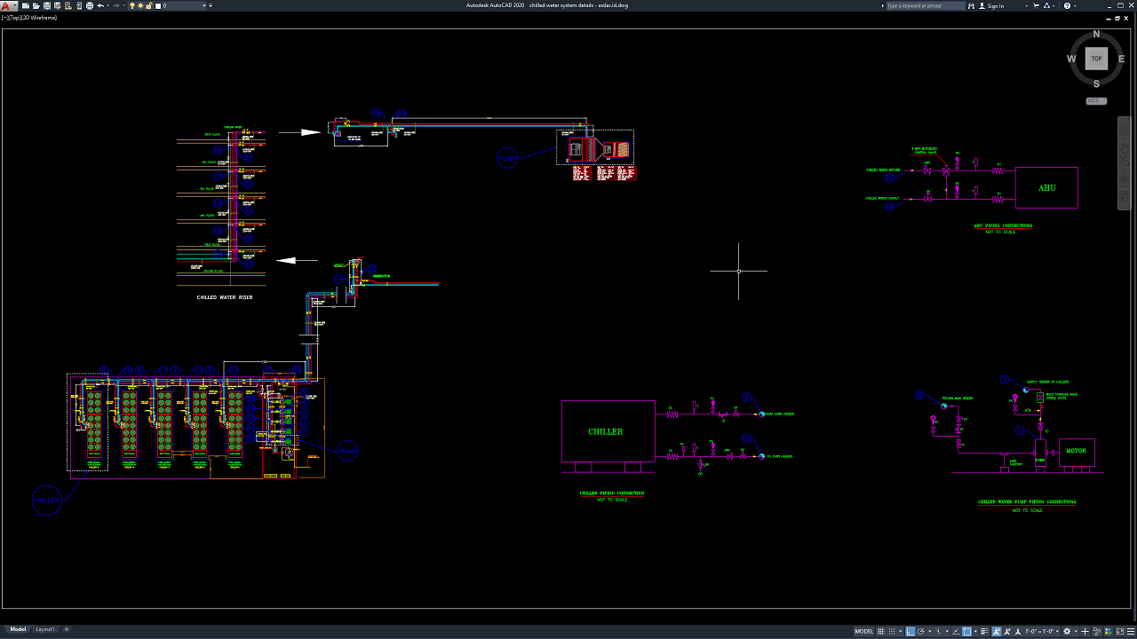
The uploaded AutoCAD drawing presents several important elements of a chilled water installation, including a chiller arrangement, piping routes, vertical chilled water risers, pump connections, and schematic piping details for equipment such as an AHU. It also shows various piping components and connection arrangements that help illustrate how the system’s equipment is interconnected. These details provide a useful visual reference for understanding the relationship between the main mechanical equipment and the distribution network.
The drawing is available as a DWG AutoCAD reference, making it suitable for reviewing technical layouts and studying HVAC piping configurations. Users can examine the drawing in compatible CAD software and adapt the reference to their project requirements after verifying the dimensions, specifications, and applicable mechanical design standards.
Function of Chilled Water System Details
Chilled water system drawings serve several important purposes during HVAC planning, design coordination, installation, and maintenance. They help engineers and construction professionals understand how the equipment and piping network should be arranged and connected within a building.
One of their primary functions is to illustrate the chilled water distribution system, including the piping routes between the chiller, pumps, risers, and air handling units. By examining the supply and return connections, engineers can better understand the intended water circulation path and coordinate the system with other mechanical services.
Another important function is to clarify equipment connection details. Chillers and pumps require suitable piping arrangements, valves, and associated components to support proper operation and maintenance. Detailed drawings help identify these connections and provide a reference for checking equipment interfaces before installation begins.
Chilled water system details are also useful for coordinating vertical risers and horizontal piping routes across different building levels. This coordination is important in commercial and high-rise buildings, where mechanical pipes must share limited space with electrical installations, plumbing systems, structural elements, and other building services.
For contractors and HVAC installers, the drawings can support installation planning, material estimation, and site coordination. AutoCAD drafters and mechanical engineers can also use the DWG file as a starting reference for preparing project-specific documentation. However, final pipe sizes, equipment capacities, flow rates, valve selections, insulation requirements, and installation dimensions must be determined from approved engineering calculations and project specifications rather than assumed from a reference drawing alone.
Download Chilled Water System Details DWG AutoCAD
Detailed Chilled Water System Details DWG AutoCAD drawings provide useful technical references for understanding HVAC chilled water distribution, equipment arrangements, piping connections, and vertical riser configurations. These drawings are particularly useful for mechanical engineers, HVAC designers, contractors, AutoCAD drafters, BIM modelers, and construction professionals involved in commercial buildings, industrial facilities, hotels, hospitals, and other projects requiring centralized cooling systems.
As shown in the uploaded drawing, the CAD sheet presents a chilled water system arrangement with chiller equipment, pump connections, chilled water risers, piping routes, and schematic connection details for an air handling unit (AHU). The drawing also illustrates chilled water piping connections to the chiller and pump, including valves and other piping components. These technical details help explain how the main cooling equipment connects to the distribution network and how chilled water is routed between different parts of the HVAC system.
These drawings provide practical references for reviewing chilled water piping layouts, equipment connections, riser arrangements, and mechanical system coordination. The chiller and pump layout helps users understand the general equipment configuration, while the riser diagram illustrates the vertical distribution of chilled water through the building. The AHU and pump connection schematics provide additional information about piping interfaces and associated components, supporting preliminary HVAC planning, installation coordination, and technical documentation.
Detailed AutoCAD DWG files allow mechanical engineers, HVAC designers, contractors, and CAD technicians to review and adapt piping routes, equipment arrangements, valve locations, and connection details according to project requirements. This drawing serves as a useful reference for chilled water system design, HVAC piping layout, chiller piping details, chilled water riser diagrams, chilled water pump connections, AHU piping connections, mechanical engineering drawings, HVAC system planning, and building services coordination. Before construction, all pipe sizes, equipment capacities, flow rates, valve specifications, dimensions, insulation requirements, and applicable mechanical standards should be verified by qualified professionals.
This drawing is available in .DWG format, which means you can open it directly in the latest version of AutoCAD or in AutoCAD 2004 and later. You can also edit and modify the drawing to suit your preferences or specific design requirements. If any labels or notations are incomplete, please feel free to add them to ensure the drawing is easy to understand.
For those of you who prefer a simpler and faster download experience on asdar.id, I also provide a Premium Member Download service that allows direct access to the original file. This way, you will not be disturbed by excessive advertisements or multiple redirect pages during the download process. If you are interested, please register HERE. Please download the Chilled Water System Details DWG AutoCAD file below:
Chilled Water System Details DWG AutoCAD
| Google Drive | DOWNLOAD[253.29KB] |
| Mediafire | DOWNLOAD[253.29KB] |
Rar password: www.asdar.id
Important Note: If you encounter a problem where the WinRAR file cannot be extracted or appears corrupted, the solution is to update the WinRAR application on your computer to the latest version. Download the latest version of WinRAR here.
If you would like to copy this article, please include the original source because I have seen some blogs repost the content without providing proper credit. Otherwise, please rewrite it using your own words. Respect and appreciate the work and effort of others.
The Chilled Water System Details DWG AutoCAD for a useful technical reference covering chilled water piping arrangements, chiller and pump connections, vertical risers, and HVAC equipment interfaces. The drawing can help mechanical engineers, HVAC designers, contractors, AutoCAD drafters, and engineering students study the layout and coordination of chilled water systems in building projects.
With its combination of equipment arrangements and piping connection details, this DWG reference can support preliminary design reviews, technical drawing development, installation coordination, and HVAC system documentation. Before using the drawing for actual construction, ensure that all dimensions, pipe sizes, flow requirements, equipment specifications, and connection details are checked and adjusted to meet the project’s engineering requirements and applicable standards.