







 asdar.id menyediakan Member Premium Download untuk download file tanpa embel-embel iklan dan halaman, apa lagi harus menunggu timer yang begitu lama. Dengan berlangganan Member Premium Download, semua file dapat didownload dengan singkat langsung menuju ke sumbernya!, klik DISINI untuk DAFTAR atau DISINI untuk LOGIN :-) Jika ada pertanyaan silahkan hubungi Admin DISINI. Untuk cara download file Member Free Download, bisa membaca Tutorial Download yang ada dibawah Timer (halaman Safelink) saat menekan tombol download.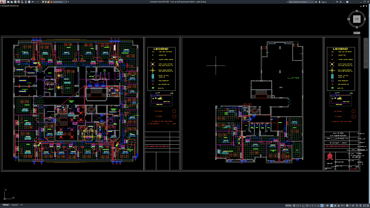
HVAC as-built drawings are important technical documents that record the final installed condition of heating, ventilation, and air-conditioning systems after construction, installation, testing, and field modifications have been completed. Unlike preliminary design drawings, as-built plans should reflect the actual locations of ductwork, air terminals, mechanical equipment, piping, control components, access points, and other HVAC elements installed within the building.
In this article, we share a reference for HVAC As-Built Layout Plan Details DWG AutoCAD that can be useful for mechanical engineers, MEP consultants, HVAC contractors, architects, facility managers, BIM coordinators, quantity surveyors, CAD technicians, construction managers, maintenance teams, and engineering students.
The drawing can serve as a practical reference for HVAC engineering services, MEP coordination, commercial HVAC installation, mechanical construction documentation, BIM coordination, HVAC maintenance planning, construction cost estimation, facility management, and building renovation projects.
What Is an HVAC As-Built Drawing?
An HVAC as-built drawing is a technical drawing that represents the HVAC system as it was actually installed on site.
During construction, conditions frequently differ from the original design. Structural beams may require duct routes to change, equipment may need to be relocated, ceiling conditions may affect diffuser positions, and piping may be rerouted to avoid clashes with electrical, plumbing, fire protection, or architectural components.
These field modifications should be recorded so that the final drawing reflects the completed installation.
Accurate as-built documentation becomes especially valuable after the building is handed over because future maintenance teams may not have direct knowledge of changes made during construction.
Importance of HVAC As-Built Layout Plans
Accurate HVAC As-Built Layout Plan Details DWG AutoCAD drawings provide a reliable record of the final mechanical installation.
They can help building owners and maintenance teams locate ducts, air-conditioning equipment, valves, dampers, access panels, piping routes, thermostats, and other mechanical components after ceilings and finishes have been completed.
Without accurate records, technicians may need to open ceilings or perform extensive inspections simply to determine where concealed systems are located.
Well-prepared as-built plans can therefore reduce maintenance time, renovation uncertainty, and future construction risk.
Download HVAC As-Built Layout Plan Details DWG AutoCAD
Proper HVAC As-Built Layout Plan Details DWG AutoCAD drawings are essential for accurately documenting the final installed locations of ductwork, air terminals, exhaust systems, ventilation equipment, dampers, thermostats, and other mechanical components within a building. Mechanical engineers, HVAC contractors, MEP consultants, facility managers, BIM coordinators, quantity surveyors, and CAD technicians must carefully coordinate duct routes, airflow distribution, equipment positions, room layouts, and ceiling-mounted components so that the completed HVAC installation can be clearly understood for operation, maintenance, and future renovation work.
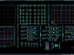
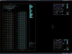
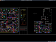
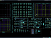
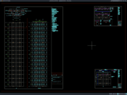
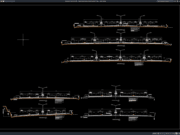
Detailed drawings such as HVAC as-built floor plans, supply air duct layouts, exhaust air systems, diffuser and grille locations, volume control dampers, ventilation fan locations, thermostat positions, airflow references, and equipment legends help engineering and maintenance teams understand the actual mechanical installation after construction. As shown in the drawing, the CAD file contains separate HVAC layout sheets for different building levels, with extensive duct routing distributed through multiple rooms and corridors. The drawings also include clearly defined legends identifying components such as exhaust fans, volume control dampers, supply ceiling diffusers, return air grilles, room thermostats, wall-mounted fans, and inline fans, together with airflow values and other system annotations.
Incomplete or inaccurate HVAC As-Built Layout Plan Details may result in difficulty locating concealed ductwork, incorrect equipment identification, maintenance delays, conflicts during renovation, inefficient troubleshooting, and unnecessary opening of ceilings or wall finishes. Accurate mechanical record drawings and proper coordination between HVAC engineers, MEP consultants, contractors, commissioning teams, facility managers, and maintenance personnel are therefore important for ensuring that the installed system can be operated, inspected, repaired, and modified efficiently throughout the building’s service life.
Detailed AutoCAD DWG files also allow engineers, contractors, and facility teams to review and update duct routes, diffuser locations, ventilation components, equipment tags, airflow information, room layouts, and other mechanical details according to verified site conditions. The drawing shown provides a practical reference for HVAC as-built documentation, ductwork layout planning, air distribution systems, mechanical ventilation coordination, MEP drafting, facility management, and building maintenance documentation.
For those of you who prefer a simpler and faster download experience on asdar.id, I also provide a Premium Member Download service that allows direct access to the original file. This way, you will not be disturbed by excessive advertisements or multiple redirect pages during the download process. If you are interested, please register HERE. Please download the HVAC As-Built Layout Plan Details DWG AutoCAD file below:
HVAC As-Built Layout Plan Details DWG AutoCAD
| Google Drive | DOWNLOAD[629.06KB] |
| Mediafire | DOWNLOAD[629.06KB] |
Rar password: www.asdar.id
Important Note: If you encounter a problem where the WinRAR file cannot be extracted or appears corrupted, the solution is to update the WinRAR application on your computer to the latest version. Download the latest version of WinRAR here.
If you would like to copy this article, please include the original source because I have seen some blogs repost the content without providing proper credit. Otherwise, please rewrite it using your own words. Respect and appreciate the work and effort of others.
HVAC As-Built Layout Plan Details DWG AutoCAD drawings provide valuable technical references for understanding and documenting the final installed condition of heating, ventilation, and air-conditioning systems.
Accurate record drawings can improve coordination between mechanical engineers, HVAC contractors, architects, MEP consultants, BIM coordinators, facility managers, quantity surveyors, commissioning teams, and maintenance technicians. They also support more reliable HVAC maintenance planning, building renovation, construction cost estimation, quantity takeoff, BIM coordination, energy audits, equipment replacement, facility management, and long-term building operation.
For building owners, a reliable HVAC as-built drawing is more than a construction record. It becomes a long-term technical asset that can reduce uncertainty, improve maintenance efficiency, and provide essential information whenever the mechanical system needs to be inspected, repaired, modified, expanded, or replaced.