





 asdar.id menyediakan Member Premium Download untuk download file tanpa embel-embel iklan dan halaman, apa lagi harus menunggu timer yang begitu lama. Dengan berlangganan Member Premium Download, semua file dapat didownload dengan singkat langsung menuju ke sumbernya!, klik DISINI untuk DAFTAR atau DISINI untuk LOGIN :-) Jika ada pertanyaan silahkan hubungi Admin DISINI. Untuk cara download file Member Free Download, bisa membaca Tutorial Download yang ada dibawah Timer (halaman Safelink) saat menekan tombol download.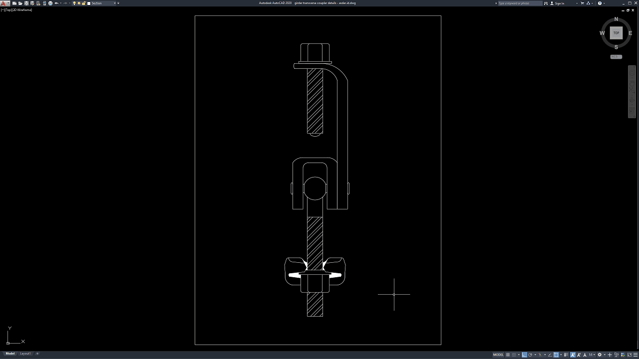
Girder Transverse Coupler Details DWG AutoCAD drawings provide a useful technical reference for understanding the configuration, geometry, and connection arrangement of a transverse coupler or girder connection component. Detailed CAD drawings are particularly valuable for engineers, fabricators, contractors, CAD technicians, and construction professionals who need to review structural connection details before fabrication or installation.
For bridge and structural projects, connection components play an important role in transferring forces and maintaining the relationship between structural members. A properly documented coupler detail can help clarify the arrangement of plates, bolts, pins, brackets, and other mechanical components used within the connection system.
What Is a Girder Transverse Coupler?
A girder transverse coupler is a connection component used to connect or restrain structural members in a transverse direction. Its exact configuration depends on the structural system, loading requirements, fabrication method, and connection design.
The coupler may incorporate components such as plates, bolts, pins, brackets, threaded elements, or other fabricated steel parts. Detailed drawings are required to communicate the geometry and relationship between these components.
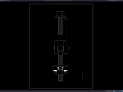
The uploaded CAD drawing presents a sectional representation of a coupler assembly, making it useful as a reference for studying the arrangement of the connection components.
Importance of Transverse Girder Connections
Structural connections must be properly coordinated because they can influence the overall behavior and constructability of a structural system. A connection needs to accommodate the required forces while maintaining the intended relationship between connected members.
For a girder system, transverse connections may assist with stability, alignment, load distribution, or structural interaction, depending on the specific engineering design.
The actual purpose and capacity of a coupler must always be verified from the project structural calculations and engineering specifications rather than assumed solely from a CAD detail.
Download Girder Transverse Coupler Details DWG AutoCAD
Proper Girder Transverse Coupler Details DWG AutoCAD drawings are useful technical references for understanding the configuration, geometry, fastening arrangement, and sectional relationship of components used in a transverse girder coupler assembly. These drawings are particularly useful for structural engineers, bridge engineers, fabricators, contractors, CAD technicians, and construction professionals involved in structural connection detailing and documentation.
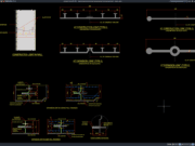
As shown in the drawing, the CAD detail presents a sectional view of a girder transverse coupler, focusing on the connection assembly and its individual components. The drawing shows a central vertical member connected through a U-shaped bracket or clevis, together with transverse pin components, plates, bolts, and fastening elements. Section hatching is also used to distinguish the cut structural components.
The upper portion of the detail shows a bolted plate connection, while the central area illustrates the bracket and pin arrangement used to connect the components. The lower portion includes additional plates and fastening elements, providing a clearer representation of how the coupler assembly is arranged vertically. These details are useful for reviewing the connection geometry and component interfaces.
The sectional representation allows engineers and fabricators to examine the relationship between the coupler, brackets, pins, plates, and bolts within a compact structural connection. Accurate coordination of these components is important to avoid dimensional conflicts and installation difficulties during fabrication or construction.
Incomplete or inaccurate Girder Transverse Coupler Details may result in incorrect component dimensions, misaligned connection holes, fastening problems, fabrication errors, or difficulties during installation. Proper coordination between structural engineers, fabricators, contractors, and CAD technicians is therefore important when developing and reviewing coupler documentation.
Detailed AutoCAD DWG files allow engineers and CAD technicians to review and adapt the coupler geometry, connection components, fastening arrangements, and sectional details according to specific project requirements and applicable engineering standards. The drawing shown provides a practical reference for girder transverse coupler detailing, structural connection details, coupler section views, bolted connections, pinned connections, steel connection components, fabrication detailing, structural CAD drafting, and construction documentation.
For those of you who prefer a simpler and faster download experience on asdar.id, I also provide a Premium Member Download service that allows direct access to the original file. This way, you will not be disturbed by excessive advertisements or multiple redirect pages during the download process. If you are interested, please register HERE. Please download the Girder Transverse Coupler Details DWG AutoCAD file below:
Girder Transverse Coupler Details DWG AutoCAD
| Google Drive | DOWNLOAD[33.81KB] |
| Mediafire | DOWNLOAD[33.81KB] |
Rar password: www.asdar.id
Important Note: If you encounter a problem where the WinRAR file cannot be extracted or appears corrupted, the solution is to update the WinRAR application on your computer to the latest version. Download the latest version of WinRAR here.
If you would like to copy this article, please include the original source because I have seen some blogs repost the content without providing proper credit. Otherwise, please rewrite it using your own words. Respect and appreciate the work and effort of others.
The Girder Transverse Coupler Details DWG AutoCAD provides a practical CAD reference for studying the configuration of a transverse coupler assembly. The drawing focuses on sectional connection geometry, including plates, brackets, bolts, pins, and other fastening components.
For structural engineers, bridge engineers, fabricators, contractors, and CAD technicians, such details can support connection drafting, fabrication coordination, technical documentation, and engineering studies. Proper professional review remains essential before adapting the drawing for an actual structural project.