




 asdar.id menyediakan Member Premium Download untuk download file tanpa embel-embel iklan dan halaman, apa lagi harus menunggu timer yang begitu lama. Dengan berlangganan Member Premium Download, semua file dapat didownload dengan singkat langsung menuju ke sumbernya!, klik DISINI untuk DAFTAR atau DISINI untuk LOGIN :-) Jika ada pertanyaan silahkan hubungi Admin DISINI. Untuk cara download file Member Free Download, bisa membaca Tutorial Download yang ada dibawah Timer (halaman Safelink) saat menekan tombol download.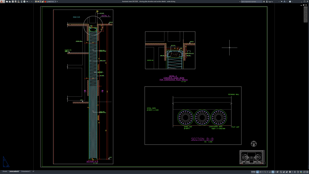
Excavation works for buildings and infrastructure projects often require temporary or permanent retaining systems to maintain excavation stability and protect adjacent structures. Shoring piles are one of the commonly used solutions for supporting excavation sides, particularly where excavation depth, site constraints, groundwater conditions, or neighboring structures require additional lateral support.
Accurate technical drawings are important for communicating the geometry, dimensions, pile arrangement, guide beam configuration, reinforcement, excavation levels, and structural details of a shoring system. For civil engineers, structural engineers, geotechnical engineers, contractors, foundation specialists, and CAD technicians, detailed CAD drawings can provide useful references for excavation support and structural documentation.
In this article, we provide a Shoring Piles Elevation and Section Details DWG AutoCAD reference that illustrates shoring pile arrangements, elevation information, pile sections, concrete guide beam details, reinforcement, excavation conditions, and related structural components.
What Are Shoring Piles?
Shoring piles are vertical structural elements installed along an excavation boundary to provide lateral support to the surrounding soil. They are commonly used where conventional sloped excavation is impractical because of limited space, adjacent buildings, roads, underground utilities, or other site constraints.q
Depending on the project requirements, shoring piles can be arranged as contiguous piles, secant piles, soldier piles with lagging, or other pile-based excavation support systems. The selection of a particular system depends on soil conditions, excavation depth, groundwater, loading, construction sequence, and the requirements of the surrounding environment.
The drawing shown in this reference specifically illustrates a contiguous pile arrangement, including a concrete guide beam and reinforcement details.
Function of Shoring Piles
The primary function of shoring piles is to provide lateral support along the excavation perimeter and help maintain the stability of the excavation face. The piles work as a retaining system that interacts with the surrounding soil and other structural components.
Shoring piles can also help reduce soil movement toward the excavation and provide protection for nearby structures, roads, and other facilities. In some projects, additional bracing, anchors, walers, struts, or guide beams may be incorporated depending on the design requirements.
The actual capacity and configuration of a shoring system must be established through appropriate geotechnical and structural analysis.
Download Shoring Piles Elevation and Section Details DWG AutoCAD
Proper Shoring Piles Elevation and Section Details DWG AutoCAD drawings are important technical references for understanding the arrangement, dimensions, reinforcement, pile configuration, and structural connections of shoring pile systems used to support excavation areas. These drawings are particularly useful for structural engineers, civil engineers, geotechnical engineers, contractors, temporary works designers, CAD technicians, BIM coordinators, and construction professionals involved in excavation support and retaining structures.
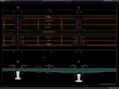
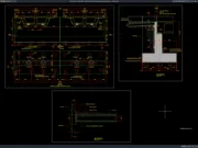
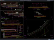
As shown in the drawing, the CAD sheet presents detailed shoring pile elevation and section views, including a vertical excavation support arrangement, contiguous piles, ground levels, excavation levels, pile dimensions, reinforcement details, concrete guide beams, retaining wall interfaces, and dimensional references. The main elevation shows a series of closely spaced vertical piles extending along the excavation depth, with structural and construction information indicated at different levels.
The main Section A-A illustrates the elevation and vertical arrangement of the shoring pile system. It shows the relationship between the existing ground level, excavation levels, adjacent structures, pile length, pile spacing, and excavation support zone. The drawing also indicates dimensions and construction references that help establish the required depth and geometry of the shoring pile installation.
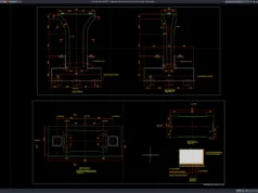
The upper-right detail provides a concrete guide beam detail for contiguous piles, showing how the pile heads are coordinated with the guide beam at the ground surface. This detail is useful for understanding the connection and alignment between adjacent piles and the supporting guide beam during construction.
The lower-right Section B-B presents a cross-sectional view of the shoring pile arrangement, showing multiple circular pile sections positioned beneath a retaining wall or guide structure. The detail includes spiral bars and longitudinal reinforcement, providing information about the internal reinforcement configuration of the reinforced concrete piles. These reinforcement details are important for coordinating pile fabrication and reinforcement installation.
Incomplete or inaccurate Shoring Piles Elevation and Section Details may result in incorrect pile alignment, insufficient excavation support, reinforcement conflicts, improper guide beam connections, construction difficulties, or coordination problems with adjacent structures. Accurate engineering drawings and proper coordination between structural engineers, geotechnical engineers, contractors, surveyors, and temporary works specialists are therefore important for developing a stable and constructible excavation support system.
Detailed AutoCAD DWG files allow engineers and CAD technicians to review and adapt shoring pile dimensions, pile spacing, excavation depths, reinforcement arrangements, guide beam details, retaining wall interfaces, and section information according to specific project requirements and applicable engineering standards. The drawing shown provides a practical reference for shoring pile design, contiguous pile walls, excavation support, pile elevation details, pile section details, pile reinforcement, concrete guide beams, retaining structures, temporary works, structural drafting, and construction documentation.
For those of you who prefer a simpler and faster download experience on asdar.id, I also provide a Premium Member Download service that allows direct access to the original file. This way, you will not be disturbed by excessive advertisements or multiple redirect pages during the download process. If you are interested, please register HERE. Please download the Shoring Piles Elevation and Section Details DWG AutoCAD file below:
Shoring Piles Elevation and Section Details DWG AutoCAD
| Google Drive | DOWNLOAD[130.18KB] |
| Mediafire | DOWNLOAD[130.18KB] |
Rar password: www.asdar.id
Important Note: If you encounter a problem where the WinRAR file cannot be extracted or appears corrupted, the solution is to update the WinRAR application on your computer to the latest version. Download the latest version of WinRAR here.
If you would like to copy this article, please include the original source because I have seen some blogs repost the content without providing proper credit. Otherwise, please rewrite it using your own words. Respect and appreciate the work and effort of others.
The Shoring Piles Elevation and Section Details DWG AutoCAD drawing provides a useful reference for understanding how a pile-based excavation support system can be represented in technical CAD documentation. The elevation view communicates the vertical arrangement of the shoring piles and excavation levels, while the section details provide additional information about pile geometry, reinforcement, and the concrete guide beam.
The drawing is particularly useful for studying contiguous shoring piles, excavation support, concrete guide beams, pile reinforcement, retaining wall interfaces, and structural section detailing. With an editable DWG format, the reference can also assist CAD users and engineering professionals in reviewing and developing project-specific documentation.
For actual construction, however, the shoring system must be designed and verified according to the specific site conditions, geotechnical investigation, structural requirements, construction methodology, and applicable engineering standards.