





 asdar.id menyediakan Member Premium Download untuk download file tanpa embel-embel iklan dan halaman, apa lagi harus menunggu timer yang begitu lama. Dengan berlangganan Member Premium Download, semua file dapat didownload dengan singkat langsung menuju ke sumbernya!, klik DISINI untuk DAFTAR atau DISINI untuk LOGIN :-) Jika ada pertanyaan silahkan hubungi Admin DISINI. Untuk cara download file Member Free Download, bisa membaca Tutorial Download yang ada dibawah Timer (halaman Safelink) saat menekan tombol download.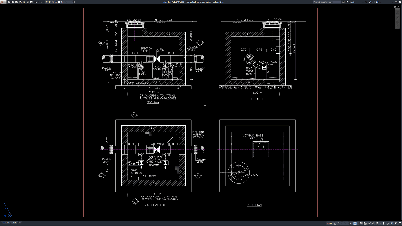
Washout valve chambers are critical components of water transmission and distribution systems because they allow pipelines to be flushed, drained, and cleaned during maintenance or emergency operations. Proper washout valve chamber design helps remove sediment, debris, and stagnant water from pipelines while protecting underground valves and ensuring long-term operational reliability.
In this article, we share a professional reference for Washout Valve Chamber Details DWG AutoCAD, which can be used by civil engineers, hydraulic engineers, water utility consultants, contractors, CAD drafters, students, and construction professionals involved in water infrastructure and pipeline projects.
What Is a Washout Valve Chamber?
A washout valve chamber is an underground reinforced concrete structure that houses a washout valve installed at low points along a water pipeline. The valve allows operators to discharge water from the pipeline for maintenance, flushing, repairs, or sediment removal.
These chambers are commonly installed in municipal water supply systems, transmission mains, irrigation pipelines, industrial water networks, and other underground utility projects.
Importance of Washout Valve Chamber Drawings
Accurate engineering drawings are essential for ensuring proper installation, maintenance accessibility, and efficient pipeline drainage.
A complete Washout Valve Chamber drawing helps engineers coordinate:
- Washout valve installation
- Pipe alignment
- Reinforced concrete chamber construction
- Drainage outlet configuration
- Foundation design
- Structural reinforcement
- Access cover placement
- Utility coordination
Proper documentation reduces installation errors while improving operational efficiency.
Download Washout Valve Chamber Details DWG AutoCAD
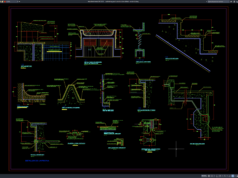
Proper Washout Valve Chamber Details drawings are essential for ensuring efficient pipeline flushing, controlled water discharge, sediment removal, and safe maintenance of water supply and transmission systems. Civil engineers, hydraulic engineers, utility designers, and pipeline contractors must carefully coordinate the washout valve location, gate valve assembly, wash pipe arrangement, pipe connections, drainage sump, thrust blocks, flexible joints, reinforced concrete chamber, access cover, and structural details to achieve a durable, safe, and standards-compliant underground washout valve installation.
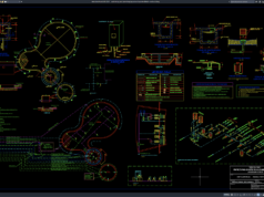
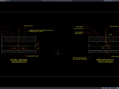
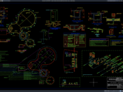
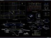
Detailed drawings such as chamber plan views, roof plans, sectional views, washout valve layouts, gate valve configurations, wash pipe details, thrust block arrangements, drainage sump configurations, pipe connection details, chamber dimensions, and construction references are important for helping engineers, contractors, utility operators, and maintenance personnel accurately understand installation requirements before construction begins. As shown in the drawing, the layout includes Section (A–A), Section (B–B), Section (C–C), roof plan, gate valve assembly, washout valve configuration, wash pipe connections, flexible joints, thrust blocks, drainage sump, reinforced concrete chamber details, and complete dimensional annotations that provide a comprehensive reference for constructing and maintaining underground washout valve chambers.
Incomplete or inaccurate Washout Valve Chamber Details drawings can result in inefficient pipeline flushing, sediment accumulation, poor drainage performance, valve misalignment, difficult maintenance access, leakage, construction conflicts, increased maintenance costs, and reduced water distribution reliability. Therefore, accurate engineering documentation and proper coordination between civil engineers, hydraulic engineers, contractors, utility operators, and construction teams are essential to ensure long-term operational safety, efficient maintenance, reliable flushing performance, and optimal operation of underground washout valve chamber systems.
Detailed AutoCAD DWG files allow civil and hydraulic engineers to modify and adapt washout valve chamber details according to project specifications, pipeline configurations, drainage requirements, structural conditions, and applicable construction standards. The drawing file shared in this article is available in DWG AutoCAD format and can be used as a practical reference for water transmission systems, municipal water supply networks, irrigation pipelines, pipeline flushing facilities, and underground utility projects. The drawing includes chamber plan views, roof plans, sectional details, washout and gate valve assemblies, wash pipe connections, flexible joints, thrust block arrangements, drainage sump details, reinforced concrete chamber construction, and dimensional references. This file is compatible with various AutoCAD versions and can be edited according to your project requirements, site conditions, and technical standards.
For those of you who prefer a simpler and faster download experience on asdar.id, I also provide a Premium Member Download service that allows direct access to the original file. This way, you will not be disturbed by excessive advertisements or multiple redirect pages during the download process. If you are interested, please register HERE. Please download the Washout Valve Chamber Details DWG AutoCAD file below:
Washout Valve Chamber Details DWG AutoCAD
| Google Drive | DOWNLOAD[806.13KB] |
| Mediafire | DOWNLOAD[806.13KB] |
Rar password: www.asdar.id
Important Note: If you encounter a problem where the WinRAR file cannot be extracted or appears corrupted, the solution is to update the WinRAR application on your computer to the latest version. Download the latest version of WinRAR here.
If you would like to copy this article, please include the original source because I have seen some blogs repost the content without providing proper credit. Otherwise, please rewrite it using your own words. Respect and appreciate the work and effort of others.
The Washout Valve Chamber Details DWG AutoCAD drawing is a valuable reference for civil engineers, hydraulic engineers, utility consultants, contractors, CAD professionals, and engineering students working on water transmission and distribution infrastructure. With complete plans, sections, reinforcement details, valve layouts, drainage configurations, and dimensional references, this DWG file helps improve engineering accuracy, construction quality, maintenance accessibility, operational efficiency, and long-term infrastructure performance. Hopefully, this drawing reference will be useful for your next water supply project, utility infrastructure development, pipeline maintenance program, or civil engineering project.
For those of you searching for Washout Valve Chamber Details working drawing references, DWG AutoCAD files are an excellent resource for water supply systems, transmission pipelines, drainage networks, hydraulic engineering, and civil engineering projects. The drawings include washout valve chamber layouts, plan and section views, gate valve details, wash pipe connections, chamber dimensions, and construction references that help engineers achieve accurate, efficient, and standards-compliant installation. If you are looking for AutoCAD files for project documentation or engineering reference, asdar.id provides a wide collection of DWG drawings related to washout valve chambers, pipeline systems, hydraulic infrastructure, utility engineering, and civil engineering projects.