





 asdar.id menyediakan Member Premium Download untuk download file tanpa embel-embel iklan dan halaman, apa lagi harus menunggu timer yang begitu lama. Dengan berlangganan Member Premium Download, semua file dapat didownload dengan singkat langsung menuju ke sumbernya!, klik DISINI untuk DAFTAR atau DISINI untuk LOGIN :-) Jika ada pertanyaan silahkan hubungi Admin DISINI. Untuk cara download file Member Free Download, bisa membaca Tutorial Download yang ada dibawah Timer (halaman Safelink) saat menekan tombol download.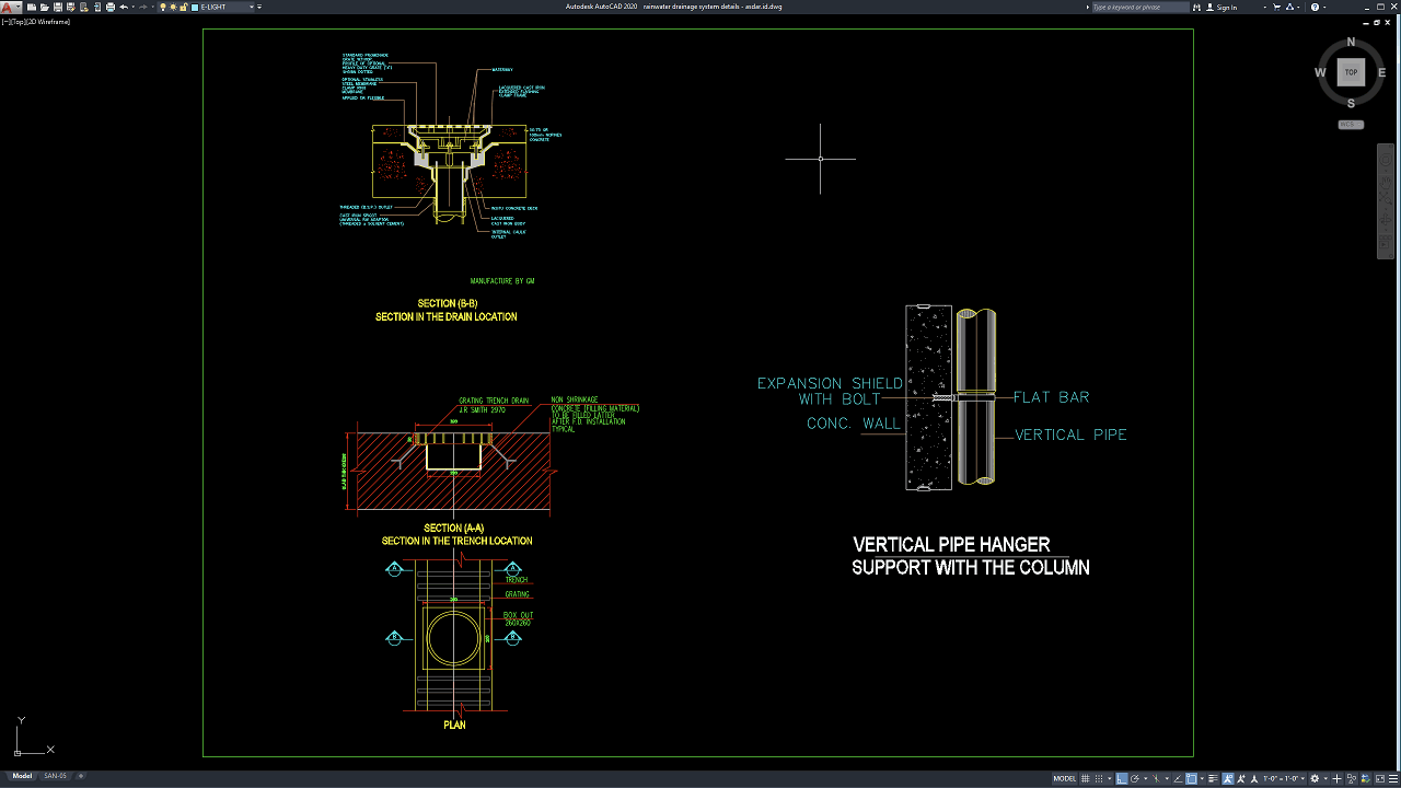
Rainwater drainage is an essential part of residential, commercial, industrial, institutional, and infrastructure projects because uncontrolled stormwater can cause flooding, structural deterioration, pavement damage, erosion, water infiltration, and long-term maintenance problems. A properly designed drainage system collects rainwater from roofs, paved areas, parking zones, walkways, and other exposed surfaces before safely conveying it toward an approved discharge point.
In this article, we share a reference for Rainwater Drainage System Details DWG AutoCAD that can be useful for civil engineers, plumbing engineers, MEP consultants, architects, drainage designers, contractors, quantity surveyors, BIM coordinators, CAD technicians, construction managers, and engineering students.
Based on the drawing, the CAD file includes practical construction references such as a storm gully or drain inlet, grating trench drain, drainage outlet connection, vertical rainwater pipe, and pipe hanger support fixed to a concrete wall or column. These details can support studies related to stormwater drainage design, plumbing engineering services, civil infrastructure, MEP coordination, construction cost estimation, quantity takeoff, BIM coordination, and building drainage construction.
What Is a Rainwater Drainage System?
A rainwater drainage system is a network of components designed to collect, convey, control, and discharge rainfall from buildings and developed sites.
Depending on the project, the system may include roof drains, gutters, downpipes, vertical rainwater pipes, trench drains, storm gullies, floor drains, catch basins, underground pipes, inspection chambers, manholes, channels, detention systems, and discharge outlets.
The primary objective is to prevent stormwater from accumulating in locations where it can damage buildings, reduce pavement performance, create safety hazards, or cause flooding.
Rainwater drainage should therefore be considered as part of the overall building and site infrastructure rather than as an isolated plumbing component.
Importance of Rainwater Drainage Details
Accurate Rainwater Drainage System Details DWG AutoCAD drawings help engineers and contractors understand how drainage components should be constructed and connected.
Small components such as gratings, pipe outlets, support brackets, trench drains, and vertical pipe fixings can have a significant effect on long-term system performance.
Incorrect installation may result in leakage, pipe movement, blocked drains, inadequate water collection, ponding, corrosion, or premature concrete deterioration.
Detailed CAD drawings improve communication between designers, contractors, fabricators, installers, inspectors, and maintenance teams.
Download Rainwater Drainage System Details DWG AutoCAD
Proper Rainwater Drainage System Details DWG AutoCAD drawings are essential for accurately coordinating stormwater inlets, trench drains, outlet connections, vertical drainage pipes, pipe supports, concrete interfaces, and associated fixing components within building and site drainage systems. Civil engineers, plumbing engineers, MEP consultants, architects, contractors, quantity surveyors, BIM coordinators, and CAD technicians must carefully coordinate drain locations, pipe sizes, finished surface levels, support arrangements, structural interfaces, and discharge connections to achieve an efficient, durable, and maintainable rainwater drainage system.
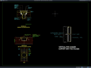
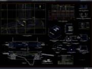
Detailed drawings such as storm gully sections, trench drain details, drainage inlet plans, grating details, pipe outlet connections, and vertical pipe support details help design and construction teams understand how individual drainage components should be installed. As shown in the drawing, the upper-left portion presents Section B-B at the drain location, illustrating a grated drainage inlet integrated with the surrounding concrete construction and connected to a vertical outlet pipe. The lower-left area includes Section A-A in the trench location together with a plan view, showing a grating trench drain, box-out area, surrounding concrete, and dimensional information. On the right, a Vertical Pipe Hanger Support with the Column detail shows a vertical pipe secured beside a concrete wall or column using a flat bar and an expansion shield with bolt.
Incorrect or incomplete Rainwater Drainage System Details may result in improperly positioned drains, inadequate surface-water collection, poorly aligned pipe outlets, weak or unsuitable pipe supports, leakage around drainage components, standing water, and difficult maintenance. Accurate drainage and MEP documentation, together with proper coordination between civil engineers, plumbing engineers, structural engineers, contractors, BIM coordinators, quantity surveyors, and site teams, is therefore important for ensuring that trench drains, stormwater inlets, vertical pipes, and supporting components are installed correctly and remain reliable during long-term operation.
Detailed AutoCAD DWG files also allow engineers and contractors to review and modify drain dimensions, grating arrangements, trench locations, outlet connections, vertical pipe positions, hanger configurations, anchor locations, and concrete interfaces according to specific project requirements. The drawing shown provides a practical reference for rainwater drainage detailing, storm gully installation, grating trench drain construction, vertical rainwater pipe support, drainage outlet coordination, MEP drainage documentation, stormwater construction detailing, and building drainage system design.
For those of you who prefer a simpler and faster download experience on asdar.id, I also provide a Premium Member Download service that allows direct access to the original file. This way, you will not be disturbed by excessive advertisements or multiple redirect pages during the download process. If you are interested, please register HERE. Please download the Rainwater Drainage System Details DWG AutoCAD file below:
Rainwater Drainage System Details DWG AutoCAD
| Google Drive | DOWNLOAD[709.50KB] |
| Mediafire | DOWNLOAD[709.50KB] |
Rar password: www.asdar.id
Important Note: If you encounter a problem where the WinRAR file cannot be extracted or appears corrupted, the solution is to update the WinRAR application on your computer to the latest version. Download the latest version of WinRAR here.
If you would like to copy this article, please include the original source because I have seen some blogs repost the content without providing proper credit. Otherwise, please rewrite it using your own words. Respect and appreciate the work and effort of others.
Rainwater Drainage System Details DWG AutoCAD drawings provide valuable technical references for understanding how storm gullies, trench drains, gratings, outlets, vertical rainwater pipes, pipe supports, anchors, and surrounding concrete construction work together within a building or site drainage system.
Accurate CAD documentation can improve coordination between civil engineers, plumbing engineers, architects, MEP consultants, contractors, BIM coordinators, quantity surveyors, and construction managers. It can also support more reliable stormwater drainage cost estimation, pipe quantity takeoff, hydraulic planning, BIM clash detection, drainage installation, maintenance planning, and construction project management.
A successful rainwater drainage system depends on more than pipe diameter alone. Surface levels, drain positions, hydraulic capacity, pipe slopes, support details, waterproofing, structural coordination, discharge points, and maintenance access must all be considered together. When these elements are properly designed and documented, the drainage system can manage rainfall more effectively while helping protect buildings, pavements, and surrounding infrastructure from water-related damage.