





 asdar.id menyediakan Member Premium Download untuk download file tanpa embel-embel iklan dan halaman, apa lagi harus menunggu timer yang begitu lama. Dengan berlangganan Member Premium Download, semua file dapat didownload dengan singkat langsung menuju ke sumbernya!, klik DISINI untuk DAFTAR atau DISINI untuk LOGIN :-) Jika ada pertanyaan silahkan hubungi Admin DISINI. Untuk cara download file Member Free Download, bisa membaca Tutorial Download yang ada dibawah Timer (halaman Safelink) saat menekan tombol download.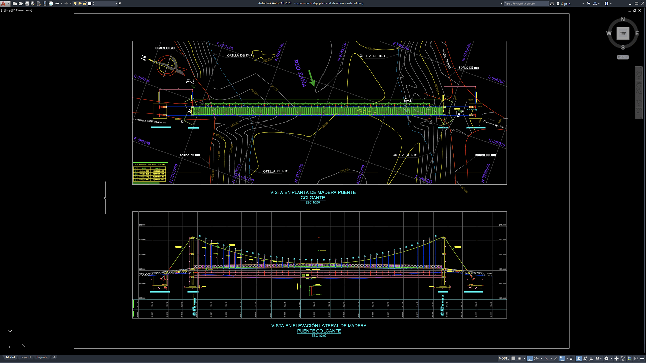
Suspension bridges are important structures in transportation infrastructure, especially for crossing rivers, valleys, roads, and other challenging terrain where long-span construction is required. Their distinctive structural system uses main suspension cables, vertical hangers, stiffening elements, towers, anchorages, and deck components to distribute loads efficiently across the bridge span. For architects, civil engineers, structural engineers, contractors, and CAD designers, accurate planning and technical drawings are essential for understanding the overall bridge configuration.
In this article, we share a Suspension Bridge Plan and Elevation DWG AutoCAD reference that can be useful for studying suspension bridge layouts, structural arrangements, dimensions, and drafting techniques. The editable CAD format allows users to review the drawing and adapt selected details to suit different project requirements.
What Is a Suspension Bridge?
A suspension bridge is a bridge structure in which the deck is supported primarily by vertical hangers connected to large main suspension cables. The main cables pass over towers and are secured to anchorages at or near the ends of the bridge. Loads from the deck are transferred through the hangers to the main cables and then distributed toward the towers and anchorages.
This structural concept makes suspension bridges particularly suitable for long spans. Depending on the project, the bridge may include pedestrian walkways, roadways, railway decks, or other transportation facilities. The final configuration depends on span length, loading requirements, site conditions, wind effects, foundation conditions, clearance requirements, and applicable design standards.
Function of a Suspension Bridge
The primary function of a suspension bridge is to provide a safe and efficient crossing over obstacles such as rivers, deep valleys, highways, railway corridors, and other areas where a long bridge span is required. Its structural system allows the bridge deck to be supported over relatively long distances using main suspension cables, vertical hangers, towers, and anchorages.
Suspension bridges are particularly suitable for locations where constructing multiple intermediate supports or piers would be difficult, costly, or impractical. By transferring loads from the deck through the hanger system to the main cables, towers, and anchorages, the structure can accommodate significant spans while maintaining sufficient clearance beneath the bridge.
Depending on the project requirements, a suspension bridge can serve pedestrians, cyclists, vehicles, or other transportation users. In addition to providing connectivity between two locations, it can improve accessibility, reduce travel distances, and support transportation networks in areas separated by natural or built obstacles.
The suspension system also provides flexibility for long-span bridge construction and can be adapted to different site conditions, architectural requirements, and transportation needs. However, its final structural configuration must be determined through detailed engineering analysis considering loads, wind, seismic conditions, foundations, cable forces, construction methods, and applicable design standards.
Download Suspension Bridge Plan and Elevation DWG AutoCAD
Proper Suspension Bridge Plan and Elevation DWG AutoCAD drawings are essential for accurately defining the layout, structural arrangement, dimensions, and elevation of suspension bridges constructed across rivers and other challenging terrains. Architects, structural engineers, civil engineers, and contractors must carefully coordinate the bridge span, deck structure, suspension cables, vertical hangers, supports, anchorage points, and connection details to ensure a safe and functional bridge design.
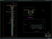
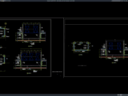
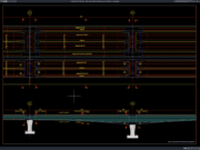
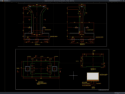
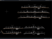
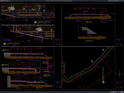
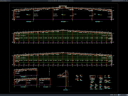
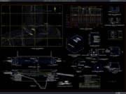
Detailed drawings such as suspension bridge plan views, lateral elevations, bridge deck layouts, main cable profiles, vertical hanger arrangements, support and anchorage details, riverbank conditions, contour information, and dimensional references help design and construction teams understand the complete bridge configuration before fabrication and construction. As shown in the drawing, the CAD layout includes a wooden suspension bridge spanning across a river, with clearly defined bridge deck components, main suspension cables, vertical hanger elements, end supports, anchorage structures, river edges, existing terrain contours, stationing, and elevation information for accurate structural planning and construction.
Incomplete or inaccurate Suspension Bridge Plan and Elevation drawings may result in incorrect bridge alignment, improper cable positioning, inadequate structural support, connection conflicts, construction difficulties, and potential safety issues. Accurate engineering drawings and proper coordination between structural engineers, civil engineers, surveyors, fabricators, and contractors are therefore important for achieving a stable, durable, and properly aligned suspension bridge.
Detailed AutoCAD DWG files also allow engineers and designers to review and modify bridge dimensions, deck arrangements, suspension cable profiles, hanger spacing, support locations, anchorage details, terrain conditions, and elevation references according to specific project requirements and applicable construction standards. The drawing shown provides a practical reference for suspension bridge design, plan and elevation documentation, structural detailing, cable arrangement, terrain coordination, and construction planning.
For those of you who prefer a simpler and faster download experience on asdar.id, I also provide a Premium Member Download service that allows direct access to the original file. This way, you will not be disturbed by excessive advertisements or multiple redirect pages during the download process. If you are interested, please register HERE. Please download the Suspension Bridge Plan and Elevation DWG AutoCAD file below:
Suspension Bridge Plan and Elevation DWG AutoCAD
| Google Drive | DOWNLOAD[324.12KB] |
| Mediafire | DOWNLOAD[324.12KB] |
Rar password: www.asdar.id
Important Note: If you encounter a problem where the WinRAR file cannot be extracted or appears corrupted, the solution is to update the WinRAR application on your computer to the latest version. Download the latest version of WinRAR here.
If you would like to copy this article, please include the original source because I have seen some blogs repost the content without providing proper credit. Otherwise, please rewrite it using your own words. Respect and appreciate the work and effort of others.
A Suspension Bridge Plan and Elevation DWG AutoCAD drawing is a useful technical reference for understanding the basic arrangement and graphical representation of suspension bridge structures. The combination of plan and elevation views makes it easier to study bridge alignment, deck configuration, tower positions, cable systems, hanger spacing, and overall structural proportions.
The editable DWG format also provides flexibility for CAD users who want to examine or adapt the drawing for educational, conceptual, or preliminary design purposes. Nevertheless, every project requires its own engineering assessment because suspension bridge design is strongly influenced by span length, loading, site conditions, foundations, environmental factors, and applicable standards.
Used correctly, a detailed CAD reference can save drafting time, improve design coordination, and provide a valuable starting point for developing more comprehensive suspension bridge documentation.