





 asdar.id menyediakan Member Premium Download untuk download file tanpa embel-embel iklan dan halaman, apa lagi harus menunggu timer yang begitu lama. Dengan berlangganan Member Premium Download, semua file dapat didownload dengan singkat langsung menuju ke sumbernya!, klik DISINI untuk DAFTAR atau DISINI untuk LOGIN :-) Jika ada pertanyaan silahkan hubungi Admin DISINI. Untuk cara download file Member Free Download, bisa membaca Tutorial Download yang ada dibawah Timer (halaman Safelink) saat menekan tombol download.
Oil industry layout plans and technical detail drawings are important references for engineers, industrial designers, CAD drafters, contractors, and project planners involved in oil processing facilities and industrial plant development.
Oil Industry Layout Plan and Details DWG AutoCAD to explore a technical drawing reference that can help users understand equipment arrangements, installation layouts, and the coordination of different components within an industrial facility.
What Is the Oil Industry?
The oil industry is a sector involved in the exploration, production, processing, storage, transportation, and distribution of oil and petroleum products. Its facilities may include processing plants, storage areas, pumping systems, pipelines, mechanical equipment, and supporting infrastructure. Each facility requires careful planning to ensure that equipment, access routes, utilities, and operational areas are arranged according to project requirements.
An Oil Industry Layout Plan and Details DWG AutoCAD drawing provides a technical reference for reviewing the spatial arrangement of industrial equipment and related installations. Depending on the project, these drawings may include equipment layouts, plan views, sectional details, dimensions, annotations, and installation information. Such documentation helps design teams understand how different components are positioned within a facility.
Function of the Oil Industry
The oil industry supports the supply of energy, fuels, lubricants, and various petroleum-based materials used in transportation, manufacturing, construction, and other economic sectors. Industrial facilities are designed to handle specific operational processes, from receiving and storing raw materials to processing and distributing finished products. Efficient facility planning helps organize equipment, improve operational access, and coordinate mechanical and structural systems.
In engineering design, layout drawings play an important role in communicating the intended arrangement of equipment and installations. They help engineers and contractors review available space, equipment positioning, maintenance access, and relationships between different plant components. These drawings can also support coordination between architectural, structural, mechanical, piping, and electrical disciplines during project development.
Download Oil Industry Layout Plan and Details DWG AutoCAD
Detailed Oil Industry Layout Plan and Details DWG AutoCAD drawings provide useful technical references for understanding the arrangement of industrial equipment, processing areas, storage units, and supporting installations within an oil-related industrial facility. These drawings are particularly useful for industrial engineers, mechanical engineers, civil engineers, piping engineers, CAD technicians, contractors, and project planners involved in industrial plant design, equipment coordination, and facility development.
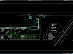
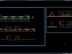
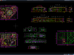
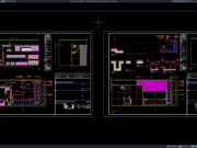
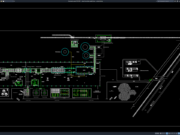
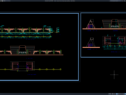
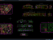
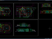
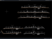
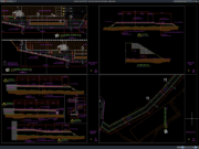
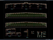
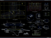
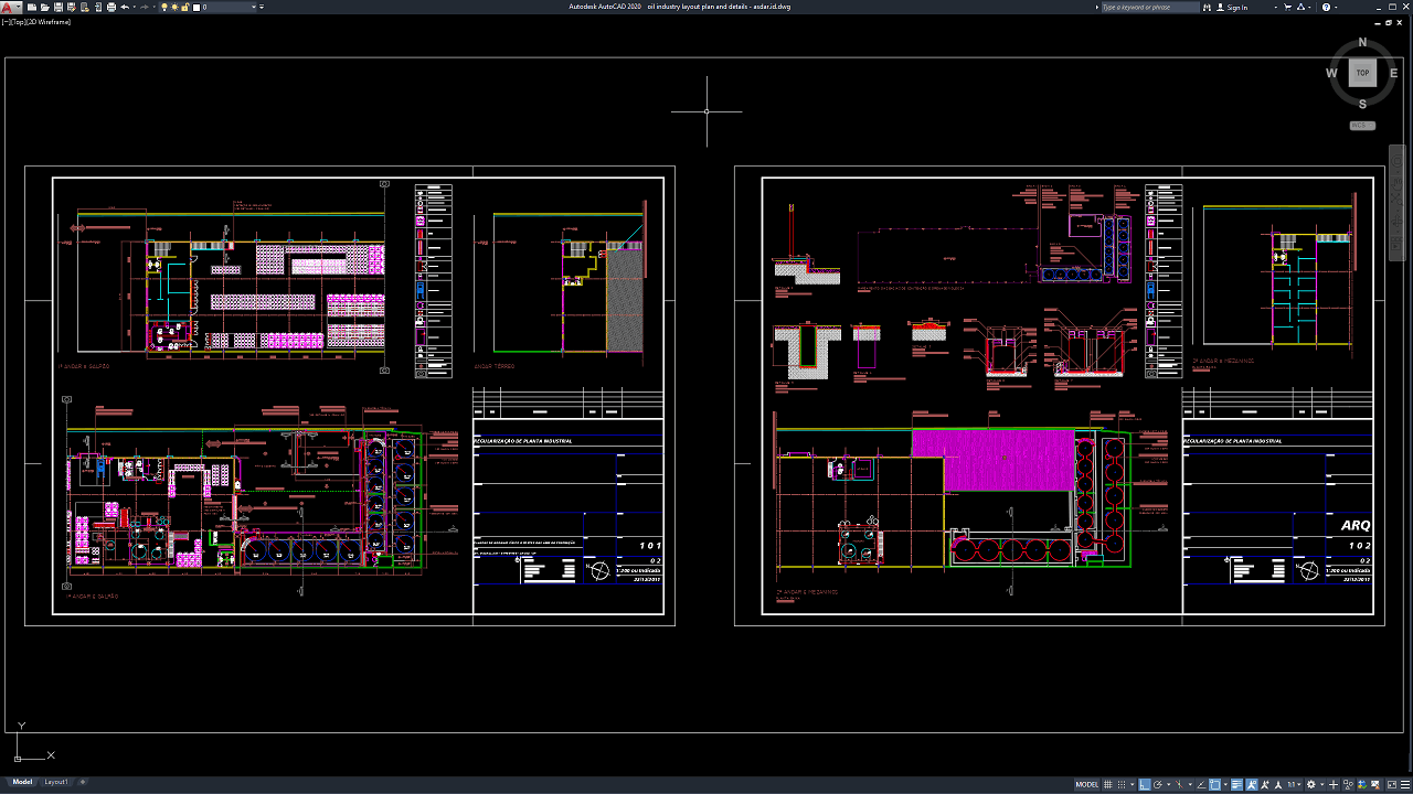
As shown in the uploaded drawing, the CAD sheet presents industrial floor layouts, equipment arrangements, sectional details, and installation views across two drawing sheets. The plans show groups of circular equipment or tank-like components arranged in rows, alongside other machinery, processing units, and supporting installations. Several enlarged details illustrate selected equipment configurations, component positions, and installation arrangements. Dimension lines, technical annotations, drawing symbols, and reference information help communicate the spatial relationships between the different elements. Although the drawing is titled as an oil industry layout, the precise function of each component and the specific industrial process should be confirmed from the original technical documentation.
These drawings provide a practical reference for reviewing equipment positioning, available working space, installation arrangements, and coordination between different industrial components. The plan views help users understand the overall layout and relationships between equipment groups, while the detailed views provide additional information about selected installations. Together, these drawing elements can support preliminary facility planning, equipment layout studies, mechanical coordination, space utilization reviews, and the preparation of technical documentation for industrial projects.
Detailed AutoCAD DWG files allow engineers, contractors, industrial designers, and CAD technicians to examine and adapt equipment locations, layout arrangements, component dimensions, and installation details according to project requirements. This drawing serves as a useful reference for oil industry layout plans, oil processing plant layouts, industrial equipment arrangements, oil plant design, mechanical installation details, industrial facility planning, equipment layout drawings, processing plant details, industrial CAD drawings, and AutoCAD plant layouts.
Before construction or equipment installation, all dimensions, equipment specifications, process requirements, piping connections, structural supports, foundation loads, utility provisions, access clearances, and safety requirements should be verified against the actual project conditions. The layout should also be coordinated with relevant process diagrams, mechanical drawings, piping plans, electrical layouts, and structural documentation. This DWG file should be treated as a planning and design reference rather than a ready-to-build engineering document.
This drawing is provided in .dwg format, which means you can open it directly using the latest version of AutoCAD or an older version, such as AutoCAD 2004. You can also edit the drawing to modify it according to your preferences or design requirements. Please note that the annotations in the drawing are written in Spanish. You may need to translate them into English or your preferred language to understand the details clearly.
For those of you who prefer a simpler and faster download experience on asdar.id, I also provide a Premium Member Download service that allows direct access to the original file. This way, you will not be disturbed by excessive advertisements or multiple redirect pages during the download process. If you are interested, please register HERE. Please download the Oil Industry Layout Plan and Details DWG AutoCAD file below:
Oil Industry Layout Plan and Details DWG AutoCAD
| Google Drive | DOWNLOAD[1.95MB] |
| Mediafire | DOWNLOAD[1.95MB] |
Rar password: www.asdar.id
Important Note: If you encounter a problem where the WinRAR file cannot be extracted or appears corrupted, the solution is to update the WinRAR application on your computer to the latest version. Download the latest version of WinRAR here.
If you would like to copy this article, please include the original source because I have seen some blogs repost the content without providing proper credit. Otherwise, please rewrite it using your own words. Respect and appreciate the work and effort of others.
The Oil Industry Layout Plan and Details DWG AutoCAD drawing provides a practical starting point for understanding industrial equipment arrangements and the presentation of technical installation details. Its plan views, component layouts, dimensions, and annotations can support preliminary design studies, CAD practice, and engineering coordination. By adapting the drawing to the specific project requirements and verifying all technical information, users can make better use of DWG references when developing industrial facility documentation.