







 asdar.id menyediakan Member Premium Download untuk download file tanpa embel-embel iklan dan halaman, apa lagi harus menunggu timer yang begitu lama. Dengan berlangganan Member Premium Download, semua file dapat didownload dengan singkat langsung menuju ke sumbernya!, klik DISINI untuk DAFTAR atau DISINI untuk LOGIN :-) Jika ada pertanyaan silahkan hubungi Admin DISINI. Untuk cara download file Member Free Download, bisa membaca Tutorial Download yang ada dibawah Timer (halaman Safelink) saat menekan tombol download.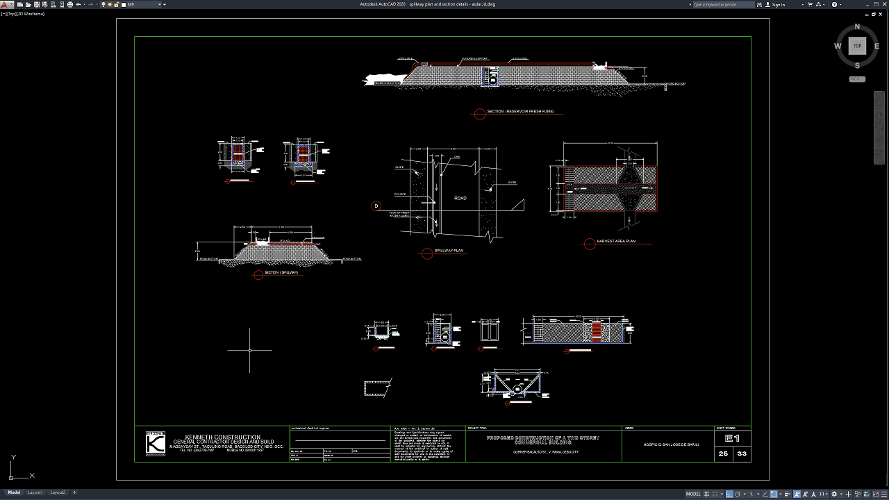
Spillways are critical hydraulic structures used to safely release excess water from dams, reservoirs, detention facilities, irrigation systems, and other water-retaining structures. Their primary purpose is to prevent uncontrolled overtopping by directing floodwater through a planned discharge route toward a downstream channel or energy-dissipation structure.
In this article, we share a reference for Spillway Plan and Section Details DWG AutoCAD that can be useful for civil engineers, hydraulic engineers, structural engineers, water-resources consultants, dam designers, contractors, quantity surveyors, BIM coordinators, CAD technicians, construction managers, and civil engineering students.
The drawing can provide a practical reference for spillway design, hydraulic engineering services, dam engineering, flood-control infrastructure, reinforced concrete structures, hydrologic analysis, construction cost estimation, quantity takeoff, BIM coordination, and water-resources construction documentation.
What Is a Spillway?
A spillway is a hydraulic structure designed to release surplus water from a reservoir or impoundment when the water level rises above a specified operating elevation.
During major rainfall events, inflow into a reservoir can exceed normal outlet capacity. Without an adequate spillway, the reservoir level could continue rising until water overtops the dam.
Uncontrolled overtopping can cause severe erosion and may threaten the stability of certain dam types.
A properly designed spillway provides a controlled path for floodwater to move from the reservoir to a safe downstream location.
The system can include an approach channel, spillway crest, control structure, chute, training walls, transition sections, stilling basin, energy-dissipation devices, drainage, and downstream protection.
Importance of Spillway Plan and Section Details
Accurate Spillway Plan and Section Details DWG AutoCAD drawings are essential for coordinating hydraulic geometry, structural dimensions, crest levels, chute alignment, retaining walls, energy-dissipation elements, foundation levels, reinforcement zones, and surrounding terrain.
The plan view explains how the structure is arranged horizontally, while longitudinal and transverse sections show how water travels vertically through the spillway.
These drawings allow hydraulic, structural, geotechnical, and construction teams to understand the structure as one coordinated system.
Incorrect dimensions or levels can significantly affect hydraulic performance.
Even relatively small changes in crest elevation, chute slope, channel width, or stilling-basin geometry can alter flow depth, velocity, discharge capacity, and downstream energy conditions.
Download Spillway Plan and Section Details DWG AutoCAD
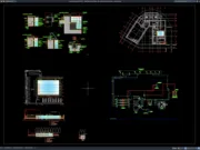
Proper Spillway Plan and Section Details DWG AutoCAD drawings are essential for accurately coordinating spillway alignment, channel width, crest and invert levels, side slopes, concrete elements, road crossings, water-flow direction, and surrounding earthworks within hydraulic and water-resources projects. Civil engineers, hydraulic engineers, structural engineers, drainage consultants, contractors, quantity surveyors, surveyors, and CAD technicians must carefully coordinate spillway dimensions, elevations, flow paths, structural components, and adjoining ground conditions to achieve a safe, efficient, and constructible water-conveyance system.
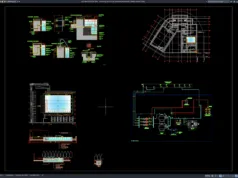
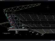
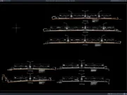
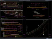
Detailed drawings such as spillway plans, longitudinal and transverse sections, channel cross sections, concrete lining details, flow-direction references, road-crossing arrangements, drainage details, and dimensional annotations help engineering and construction teams understand the complete hydraulic structure before excavation and concrete work begin. As shown in the drawing, the CAD sheet includes a clearly identified Spillway Plan showing the spillway crossing beneath or adjacent to a road and indicating the direction of fresh-water flow, together with a dedicated Section (Spillway) illustrating the channel profile, side embankments, structural dimensions, and surrounding ground. Additional sections and enlarged construction details provide further information on the associated channel, concrete surfaces, openings, and adjacent site elements.
Incomplete or inaccurate Spillway Plan and Section Details may result in incorrect channel dimensions, unsuitable invert elevations, inadequate flow capacity, poorly coordinated road crossings, improper side-slope construction, drainage problems, erosion, and costly site modifications. Accurate hydraulic and civil engineering documentation, together with proper coordination between hydraulic engineers, structural engineers, geotechnical specialists, contractors, quantity surveyors, surveyors, and site teams, is therefore important for achieving reliable water conveyance and durable spillway construction.
Detailed AutoCAD DWG files also allow engineers and contractors to review and modify spillway alignment, channel widths, section profiles, invert and crest elevations, side slopes, concrete components, road interfaces, and other hydraulic details according to specific site and design requirements. The drawing shown provides a practical reference for spillway planning, hydraulic channel design, spillway cross-section detailing, reinforced concrete coordination, road-crossing drainage, water-flow management, civil infrastructure documentation, and hydraulic construction drafting.
For those of you who prefer a simpler and faster download experience on asdar.id, I also provide a Premium Member Download service that allows direct access to the original file. This way, you will not be disturbed by excessive advertisements or multiple redirect pages during the download process. If you are interested, please register HERE. Please download the Spillway Plan and Section Details DWG AutoCAD file below:
Spillway Plan and Section Details DWG AutoCAD
| Google Drive | DOWNLOAD[177.59KB] |
| Mediafire | DOWNLOAD[177.59KB] |
Rar password: www.asdar.id
Important Note: If you encounter a problem where the WinRAR file cannot be extracted or appears corrupted, the solution is to update the WinRAR application on your computer to the latest version. Download the latest version of WinRAR here.
If you would like to copy this article, please include the original source because I have seen some blogs repost the content without providing proper credit. Otherwise, please rewrite it using your own words. Respect and appreciate the work and effort of others.
Spillway Plan and Section Details DWG AutoCAD drawings provide valuable technical references for understanding how spillway crests, channels, chute slabs, training walls, stilling basins, foundations, drainage systems, and downstream protection work together within a hydraulic structure.
Accurate CAD documentation can improve coordination between hydraulic engineers, structural engineers, geotechnical consultants, dam designers, contractors, BIM coordinators, quantity surveyors, and construction managers. It can also support more reliable spillway construction cost estimation, concrete and reinforcement quantity takeoff, hydrologic planning, hydraulic modeling, BIM coordination, construction scheduling, dam-safety evaluation, and long-term infrastructure maintenance.
A successful spillway must safely pass the required flood discharge while controlling velocity, structural forces, uplift, erosion, and downstream energy. When hydraulic, structural, geotechnical, and construction requirements are coordinated correctly, the spillway becomes one of the most important systems protecting a dam and its downstream communities.