








 asdar.id menyediakan Member Premium Download untuk download file tanpa embel-embel iklan dan halaman, apa lagi harus menunggu timer yang begitu lama. Dengan berlangganan Member Premium Download, semua file dapat didownload dengan singkat langsung menuju ke sumbernya!, klik DISINI untuk DAFTAR atau DISINI untuk LOGIN :-) Jika ada pertanyaan silahkan hubungi Admin DISINI. Untuk cara download file Member Free Download, bisa membaca Tutorial Download yang ada dibawah Timer (halaman Safelink) saat menekan tombol download.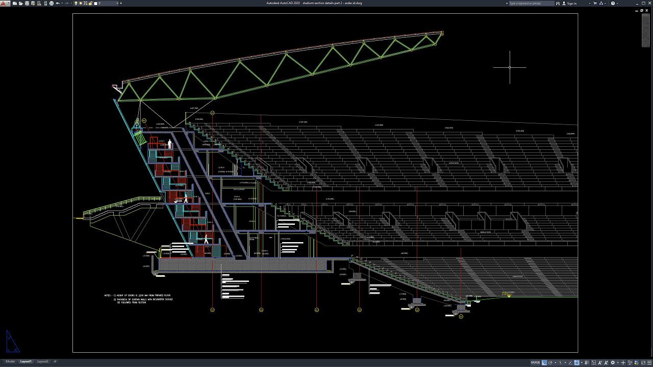
Stadium section drawings are essential architectural and engineering documents used to understand the vertical relationship between seating tiers, spectator circulation, structural framing, roof systems, playing areas, concourses, service spaces, foundations, and other major building components. Unlike floor plans, which primarily show horizontal arrangements, section drawings reveal how different stadium levels connect vertically and how structural and architectural elements work together.
In this article, we share a reference for Stadium Section Details Part 2 DWG AutoCAD that can be useful for architects, civil engineers, structural engineers, stadium designers, sports facility consultants, contractors, quantity surveyors, BIM coordinators, CAD technicians, construction managers, and architecture or engineering students.
The drawing can provide a practical reference for stadium architectural design, grandstand engineering, sports facility planning, structural engineering services, stadium roof design, BIM coordination, construction cost estimation, quantity takeoff, commercial construction management, and large-scale public building documentation.
What Is a Stadium Section Drawing?
A stadium section drawing is a vertical cut through a stadium that shows how different building levels, seating areas, structural components, circulation routes, and roof elements relate to one another.
A section may pass through the grandstand, playing field, concourse, VIP area, roof structure, staircases, ramps, service rooms, or other important parts of the stadium.
These drawings help designers understand building height, floor-to-floor dimensions, spectator sightlines, seating rake, structural depth, roof clearance, and vertical circulation.
They are especially important in stadium projects because the building geometry is usually much more complex than a conventional commercial or residential building.
Importance of Stadium Section Details
Accurate Stadium Section Details Part 2 DWG AutoCAD drawings help architects and engineers coordinate seating, structure, circulation, roof framing, MEP services, floor levels, and spectator spaces before construction begins.
A stadium contains many repeated but highly coordinated components. Small errors in seating geometry, riser heights, beam depth, roof clearance, or circulation levels can create major problems when repeated across thousands of spectator seats.
Section drawings therefore provide a critical reference for resolving these relationships before structural fabrication and construction.
They also support clearer communication between architects, structural engineers, MEP consultants, contractors, stadium operators, and quantity surveyors.
Download Stadium Section Details Part 2 DWG AutoCAD
Proper Stadium Section Details Part 2 DWG AutoCAD drawings are essential for accurately coordinating multi-tier grandstand seating, roof trusses, floor levels, stair cores, concourse areas, structural framing, support columns, and foundation elements within large sports facility projects. Architects, structural engineers, civil engineers, stadium designers, contractors, quantity surveyors, BIM coordinators, and CAD technicians must carefully coordinate seating geometry, roof clearances, vertical circulation, structural levels, internal spaces, and load-bearing components to achieve a safe, functional, and constructible stadium structure.
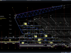
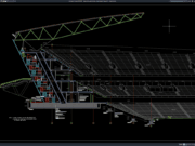
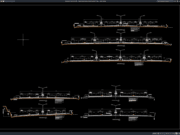
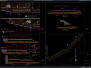
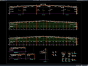
Detailed drawings such as stadium cross sections, grandstand seating profiles, roof truss sections, stair and circulation details, concourse levels, structural support arrangements, foundation zones, and dimensional references help design and construction teams understand the complete vertical organization of the stadium before construction begins. As shown in the drawing, the CAD sheet presents a large stadium section with several stacked seating tiers, stepped spectator rows, multiple aisle and vomitory openings, internal floor levels beneath the grandstands, and a prominent inclined steel roof truss spanning above the upper seating area. The left side also shows a multi-level vertical circulation core with stairs and connecting floor platforms, together with structural supports and service spaces positioned below the grandstand.
Incomplete or inaccurate Stadium Section Details Part 2 may result in unsuitable seating gradients, incorrect floor elevations, insufficient headroom, conflicts between roof framing and seating structures, poorly coordinated stair circulation, misaligned structural supports, and costly construction rework. Accurate architectural and structural documentation, together with proper coordination between stadium architects, structural engineers, MEP consultants, steel fabricators, contractors, quantity surveyors, and site teams, is therefore important for achieving safe spectator circulation, efficient structural load transfer, and reliable stadium construction.
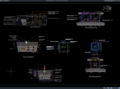
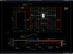
Detailed AutoCAD DWG files also allow designers, engineers, and contractors to review and modify seating tier profiles, grandstand levels, stair geometry, concourse elevations, roof truss arrangements, structural grids, internal room layouts, and foundation details according to specific stadium requirements. The drawing shown provides a practical reference for stadium section design, multi-tier grandstand detailing, seating bowl planning, steel roof truss coordination, stadium vertical circulation, sports facility architecture, structural documentation, and large-scale construction drafting.
For those of you who prefer a simpler and faster download experience on asdar.id, I also provide a Premium Member Download service that allows direct access to the original file. This way, you will not be disturbed by excessive advertisements or multiple redirect pages during the download process. If you are interested, please register HERE. Please download the Stadium Section Details Part 2 DWG AutoCAD file below:
Stadium Section Details Part 2 DWG AutoCAD
| Google Drive | DOWNLOAD[312.60KB] |
| Mediafire | DOWNLOAD[312.60KB] |
Rar password: www.asdar.id
Important Note: If you encounter a problem where the WinRAR file cannot be extracted or appears corrupted, the solution is to update the WinRAR application on your computer to the latest version. Download the latest version of WinRAR here.
If you would like to copy this article, please include the original source because I have seen some blogs repost the content without providing proper credit. Otherwise, please rewrite it using your own words. Respect and appreciate the work and effort of others.
Stadium Section Details Part 2 DWG AutoCAD drawings provide valuable references for understanding how seating tiers, grandstands, concourses, circulation, structural framing, roofs, floor levels, and support spaces work together within a stadium.
Accurate CAD documentation can improve collaboration between architects, structural engineers, sports consultants, MEP engineers, contractors, steel fabricators, BIM coordinators, quantity surveyors, and construction managers. It can also support more reliable stadium construction cost estimation, structural steel quantity takeoff, reinforced concrete planning, BIM clash detection, roof engineering, seating design, construction scheduling, and sports facility development.
A successful stadium should combine clear spectator sightlines, safe crowd circulation, efficient structural systems, reliable MEP infrastructure, durable materials, and long-term operational flexibility. When these elements are carefully coordinated through accurate section drawings, the result can be a safer, more efficient, and more enjoyable sports venue.