





 asdar.id menyediakan Member Premium Download untuk download file tanpa embel-embel iklan dan halaman, apa lagi harus menunggu timer yang begitu lama. Dengan berlangganan Member Premium Download, semua file dapat didownload dengan singkat langsung menuju ke sumbernya!, klik DISINI untuk DAFTAR atau DISINI untuk LOGIN :-) Jika ada pertanyaan silahkan hubungi Admin DISINI. Untuk cara download file Member Free Download, bisa membaca Tutorial Download yang ada dibawah Timer (halaman Safelink) saat menekan tombol download.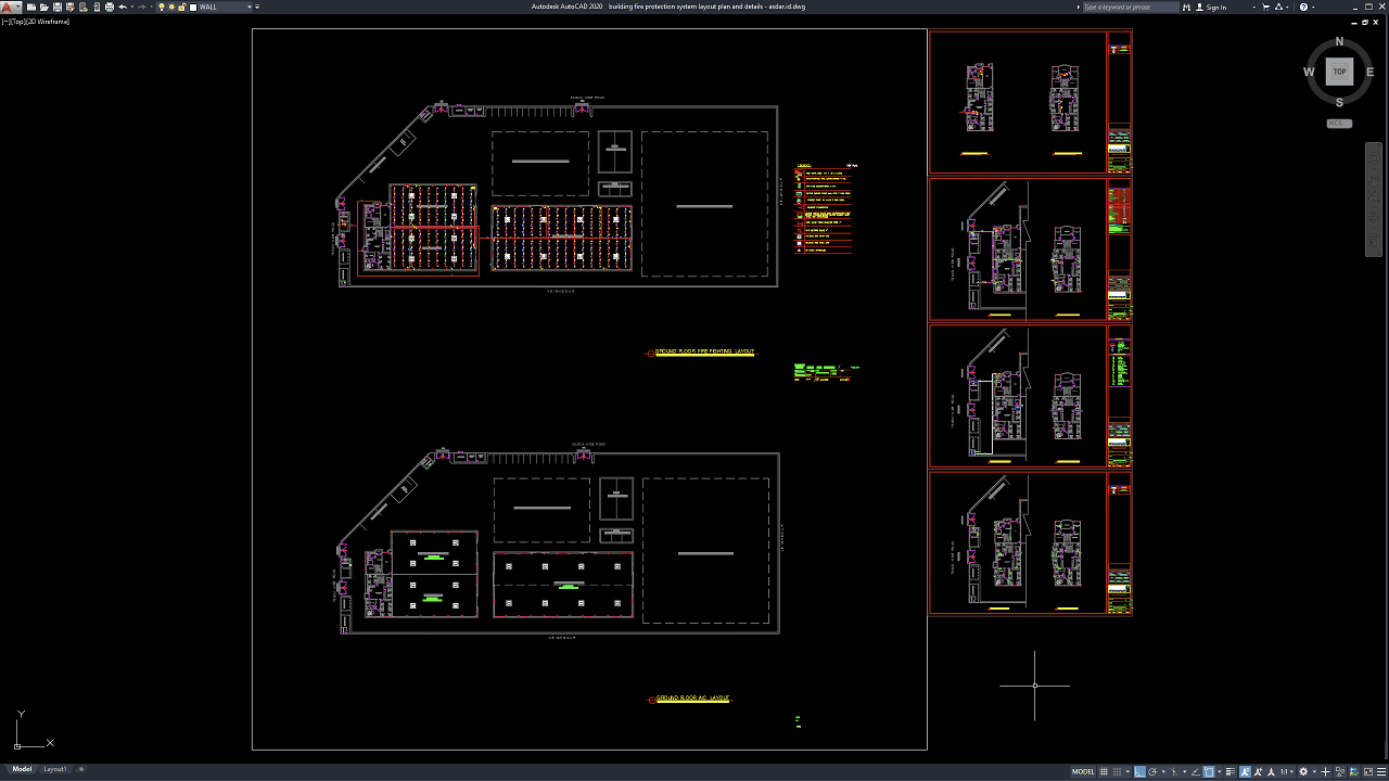
A building fire protection system is one of the most important life-safety components in residential, commercial, industrial, institutional, hospitality, healthcare, and public buildings. A properly designed system helps detect, control, suppress, and manage fire incidents while supporting safe evacuation and protecting property.
In this article, we share a reference for Building Fire Protection System Layout Plan and Details DWG AutoCAD that can be useful for architects, fire protection engineers, MEP consultants, mechanical engineers, electrical engineers, civil engineers, contractors, quantity surveyors, BIM coordinators, CAD technicians, construction managers, facility managers, and engineering students.
The drawing can provide a practical reference for fire protection engineering services, sprinkler system design, fire hydrant systems, fire alarm coordination, MEP engineering, BIM coordination services, construction cost estimation, quantity takeoff, commercial building design, and fire safety project management.
What Is a Building Fire Protection System?
A building fire protection system is a combination of active and passive safety measures designed to reduce the risk of injury, loss of life, and property damage during a fire.
Active systems may include automatic sprinklers, fire hydrants, hose reels, portable extinguishers, fire alarms, smoke detectors, fire pumps, water-storage tanks, and emergency notification systems.
Passive systems can include fire-rated walls, fire doors, protected shafts, compartmentation, structural fire protection, and smoke barriers.
Both active and passive systems should be coordinated with the architectural and structural design of the building.
Importance of Fire Protection Drawings
Proper Building Fire Protection System Layout Plan and Details DWG AutoCAD drawings are essential because fire-safety systems must function reliably during emergency conditions.
Incorrect equipment positioning can reduce coverage. Poorly coordinated pipe routes can conflict with structural or MEP elements.
Improper valve arrangements may make maintenance difficult. Missing system components can compromise fire-safety performance.
Detailed CAD drawings help engineers, contractors, inspectors, and facility managers understand how the complete system should be installed and operated.
Download Building Fire Protection System Layout Plan and Details DWG AutoCAD
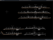
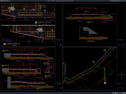
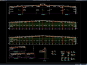
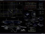
Proper Building Fire Protection System Layout Plan and Details DWG AutoCAD drawings are essential for accurately coordinating sprinkler networks, fire-fighting pipe routes, fire protection equipment locations, riser connections, valves, service zones, and building floor layouts within residential, commercial, and institutional projects. Fire protection engineers, MEP consultants, mechanical engineers, architects, contractors, quantity surveyors, BIM coordinators, and CAD technicians must carefully coordinate pipe routing, sprinkler coverage, equipment positions, ceiling conditions, structural elements, and access requirements to achieve a reliable, maintainable, and properly organized fire protection system.
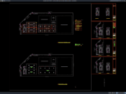
Detailed drawings such as fire fighting floor plans, sprinkler layouts, fire pipe routing plans, equipment locations, riser connections, legends, typical details, and floor-by-floor fire protection plans help design and construction teams understand how the system is distributed throughout the building. As shown in the drawing, the CAD sheet includes a clearly identified Ground Floor Fire Fighting Layout in the upper-left area, where dense and regularly spaced fire-protection lines and repeated symbols are arranged across two large rectangular building zones. A separate legend is positioned near the center of the sheet, while the right side contains several additional smaller floor plans and technical sheets that provide supplementary information for coordinating the fire protection system across different building areas and levels.
Incorrect or incomplete Building Fire Protection System Layout Plan and Details may result in insufficient sprinkler coverage, poorly coordinated pipe routes, inaccessible valves, conflicts with structural or mechanical systems, difficult maintenance, and costly modifications during construction. Accurate fire protection and MEP documentation, together with proper coordination between fire protection engineers, mechanical engineers, architects, contractors, BIM coordinators, quantity surveyors, and site teams, is therefore important for ensuring that fire-fighting components are installed in the correct locations and that the system can operate effectively when required.
Detailed AutoCAD DWG files also allow engineers and contractors to review and modify sprinkler positions, pipe routing, fire-fighting zones, equipment locations, riser connections, legends, and floor-level layouts according to specific project requirements. The drawing shown provides a practical reference for building fire protection planning, sprinkler system layout, fire-fighting piping coordination, floor-by-floor fire protection documentation, MEP coordination, fire protection quantity takeoff, construction drafting, and building fire safety system design.
For those of you who prefer a simpler and faster download experience on asdar.id, I also provide a Premium Member Download service that allows direct access to the original file. This way, you will not be disturbed by excessive advertisements or multiple redirect pages during the download process. If you are interested, please register HERE. Please download the Building Fire Protection System Layout Plan and Details DWG AutoCAD file below:
Building Fire Protection System Layout Plan and Details DWG AutoCAD
| Google Drive | DOWNLOAD[279.14KB] |
| Mediafire | DOWNLOAD[279.14KB] |
Rar password: www.asdar.id
Important Note: If you encounter a problem where the WinRAR file cannot be extracted or appears corrupted, the solution is to update the WinRAR application on your computer to the latest version. Download the latest version of WinRAR here.
If you would like to copy this article, please include the original source because I have seen some blogs repost the content without providing proper credit. Otherwise, please rewrite it using your own words. Respect and appreciate the work and effort of others.
Building Fire Protection System Layout Plan and Details DWG AutoCAD drawings provide valuable technical references for understanding how sprinklers, hydrants, hose reels, fire pumps, tanks, valves, pipes, alarm devices, and related life-safety systems are coordinated throughout a building.
Accurate CAD documentation can improve collaboration between fire protection engineers, MEP consultants, architects, structural engineers, electrical engineers, contractors, BIM coordinators, quantity surveyors, construction managers, and facility operators. It can also support more reliable fire protection cost estimation, sprinkler quantity takeoff, hydraulic analysis, BIM clash detection, fire-pump planning, system commissioning, construction scheduling, and long-term maintenance.
A successful building fire-protection system depends on more than installing individual safety devices. Water supply, hydraulic performance, alarm integration, equipment access, fire compartmentation, emergency evacuation, maintenance, and multidisciplinary coordination must all work together. When these elements are properly designed and documented, the fire-protection system can provide a more reliable level of life safety and property protection throughout the building’s service life.