




 asdar.id menyediakan Member Premium Download untuk download file tanpa embel-embel iklan dan halaman, apa lagi harus menunggu timer yang begitu lama. Dengan berlangganan Member Premium Download, semua file dapat didownload dengan singkat langsung menuju ke sumbernya!, klik DISINI untuk DAFTAR atau DISINI untuk LOGIN :-) Jika ada pertanyaan silahkan hubungi Admin DISINI. Untuk cara download file Member Free Download, bisa membaca Tutorial Download yang ada dibawah Timer (halaman Safelink) saat menekan tombol download.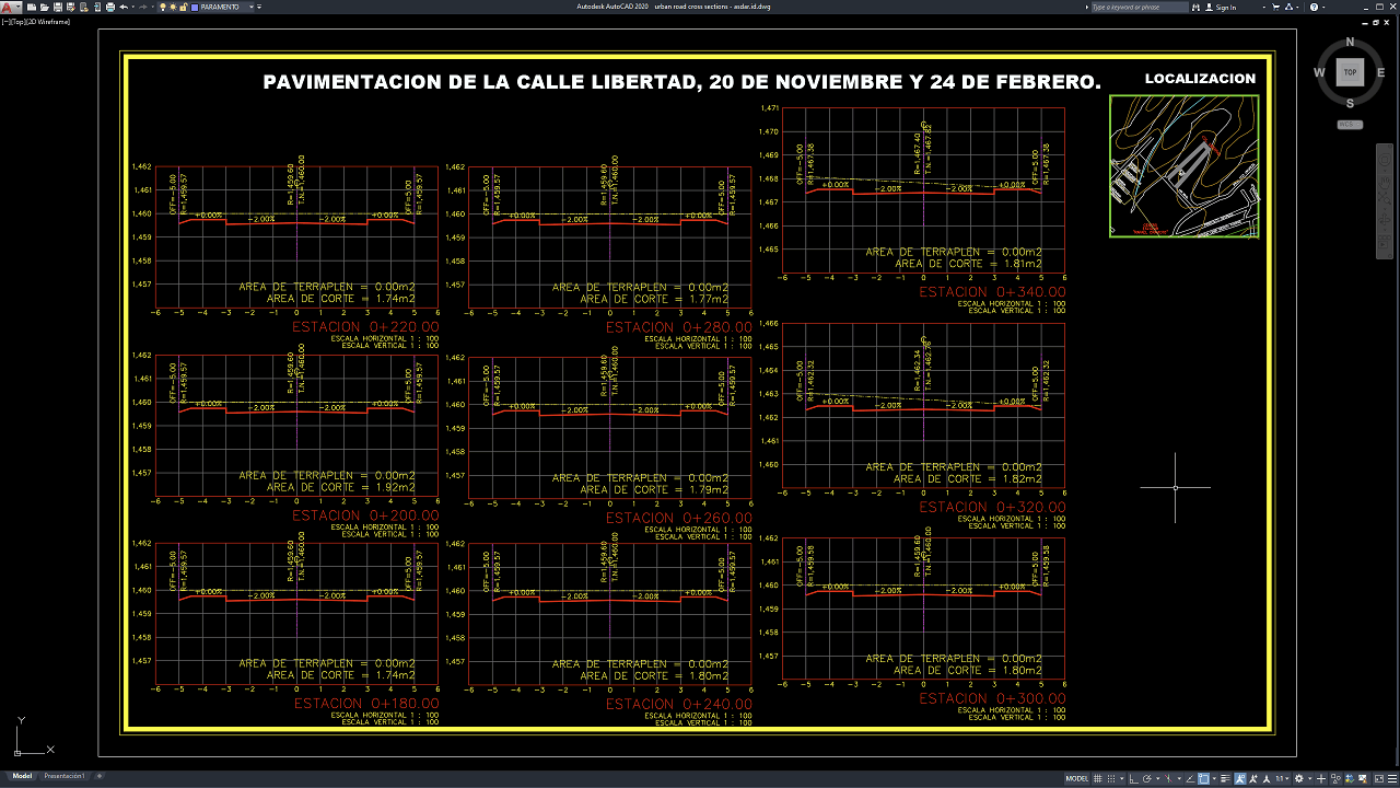
Urban Road Cross Sections DWG AutoCAD drawings provide useful technical references for understanding road geometry, pavement structure, lane configuration, sidewalk dimensions, drainage systems, and roadside facilities in urban environments. These CAD drawings are valuable for civil engineers, highway engineers, road designers, transportation planners, contractors, CAD technicians, BIM modelers, quantity surveyors, and civil engineering students involved in road infrastructure projects.
Urban road design requires careful coordination between traffic lanes, pedestrian facilities, drainage infrastructure, utility corridors, and adjacent properties. Cross-sectional drawings help communicate the dimensions and arrangement of these elements, allowing engineers and construction teams to review the proposed road profile before implementation.
What Are Urban Road Cross Sections?
Urban road cross sections are technical drawings that illustrate the arrangement of road components when viewed across the road’s width. They show the relative positions, dimensions, elevations, slopes, and construction layers of the roadway and its surrounding facilities.
Depending on the project, a typical urban road cross section may include traffic lanes, medians, shoulders, curbs, sidewalks, cycle lanes, roadside drainage channels, utility zones, and pavement layers. The configuration varies according to the road classification, traffic demand, available right-of-way, pedestrian requirements, and local design standards.
Cross-sectional drawings may also identify the road centerline, carriageway width, crossfall, finished surface levels, pavement thicknesses, and ground levels. These details help establish the relationship between the road surface, drainage system, and adjacent land.
Urban Road Cross Sections DWG AutoCAD files provide a practical digital reference for reviewing these geometric and construction elements. Engineers and CAD technicians can use the drawings to study typical road configurations and prepare project-specific documentation in compatible CAD software.
Functions of Urban Road Cross Sections
Urban road cross sections serve several important purposes during road planning, engineering design, and construction.
1. Defining Road Geometry
Cross sections communicate the width and arrangement of traffic lanes, medians, shoulders, sidewalks, and other road elements. This information helps engineers verify whether the proposed configuration meets the intended road function and available right-of-way.
2. Detailing Pavement Structure
Pavement cross sections can illustrate the arrangement of asphalt or concrete surfacing, base courses, subbase layers, and prepared subgrade. These layers must be designed according to traffic loading, soil conditions, drainage requirements, and the applicable pavement design method.
3. Coordinating Road Drainage
Road crossfall and surface elevations influence how rainwater flows toward gutters, inlets, and drainage channels. Cross-sectional details help designers coordinate these elements and reduce the risk of standing water on the roadway or pedestrian areas.
4. Providing Safe Pedestrian Facilities
Urban road sections can show sidewalks, curbs, pedestrian zones, and cycle facilities where applicable. Their dimensions and positions should be coordinated with accessibility requirements, pedestrian movement, traffic safety, and surrounding development.
5. Supporting Construction and Quantity Estimation
Detailed cross sections provide geometric information that can assist with earthwork calculations, pavement quantity estimates, curb construction, and drainage installation. Accurate quantities should be calculated using the complete design drawings and verified project data.
Download Urban Road Cross Sections DWG AutoCAD
Detailed Urban Road Cross Sections DWG AutoCAD drawings provide useful technical references for understanding road surface profiles, cross-sectional geometry, pavement gradients, elevation levels, and earthwork calculations along an urban roadway. These drawings are particularly useful for civil engineers, road design engineers, highway engineers, surveyors, contractors, CAD technicians, and construction professionals involved in road planning, geometric design, and infrastructure development.
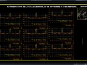
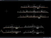
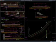
As shown in the drawing, the CAD sheet presents multiple urban road cross sections at different chainage stations, including stations 0+180.00, 0+200.00, 0+220.00, 0+240.00, 0+260.00, 0+280.00, 0+300.00, 0+320.00, and 0+340.00. Each section is displayed on a coordinate grid with elevation levels, station labels, and a red line representing the proposed road profile. The cross sections illustrate the road surface configuration, transverse gradients, and elevation differences across the roadway. The drawing also includes cut and fill area calculations, horizontal and vertical scale information, and a location plan that identifies the road alignment within the surrounding area.
These drawings provide a practical reference for reviewing road geometry, crossfall gradients, surface elevations, and changes in the proposed road profile along the alignment. The station-by-station cross sections help engineers assess earthwork requirements, compare existing ground levels with proposed road levels, and estimate cut and fill quantities. The elevation annotations, grid lines, and slope percentages also support the review of road surface consistency and the coordination of design information during the planning and construction stages.
Detailed AutoCAD DWG files allow civil engineers, road designers, surveyors, and CAD technicians to review and adapt cross-sectional profiles, station elevations, transverse slopes, and earthwork information according to project requirements. The drawing serves as a useful reference for urban road cross sections, road profile drawings, roadway elevation details, road crossfall design, road alignment, cut and fill calculations, earthwork estimation, urban road design, civil engineering CAD drawings, and road construction documentation.
For those of you who prefer a simpler and faster download experience on asdar.id, I also provide a Premium Member Download service that allows direct access to the original file. This way, you will not be disturbed by excessive advertisements or multiple redirect pages during the download process. If you are interested, please register HERE. Please download the Urban Road Cross Sections DWG AutoCAD file below:
Urban Road Cross Sections DWG AutoCAD
| Google Drive | DOWNLOAD[4.18MB] |
| Mediafire | DOWNLOAD[4.18MB] |
Rar password: www.asdar.id
Important Note: If you encounter a problem where the WinRAR file cannot be extracted or appears corrupted, the solution is to update the WinRAR application on your computer to the latest version. Download the latest version of WinRAR here.
If you would like to copy this article, please include the original source because I have seen some blogs repost the content without providing proper credit. Otherwise, please rewrite it using your own words. Respect and appreciate the work and effort of others.
Urban Road Cross Sections DWG AutoCAD drawings provide a practical reference for understanding road geometry, pavement layers, sidewalk arrangements, drainage systems, and other components of urban road infrastructure.
For civil engineers, road designers, highway engineers, contractors, CAD technicians, and engineering students, these drawings can support technical drafting, design coordination, preliminary quantity estimation, and construction planning. However, reference drawings should not replace project-specific engineering design. Road dimensions, pavement specifications, drainage requirements, and accessibility provisions must be verified by qualified professionals in accordance with applicable standards and project conditions.