





 asdar.id menyediakan Member Premium Download untuk download file tanpa embel-embel iklan dan halaman, apa lagi harus menunggu timer yang begitu lama. Dengan berlangganan Member Premium Download, semua file dapat didownload dengan singkat langsung menuju ke sumbernya!, klik DISINI untuk DAFTAR atau DISINI untuk LOGIN :-) Jika ada pertanyaan silahkan hubungi Admin DISINI. Untuk cara download file Member Free Download, bisa membaca Tutorial Download yang ada dibawah Timer (halaman Safelink) saat menekan tombol download.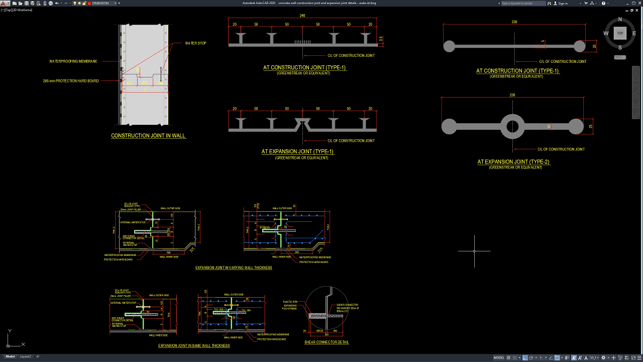
Proper Concrete Wall Construction Joint and Expansion Joint Details DWG AutoCAD drawings are important technical references for understanding how reinforced concrete walls are separated, connected, and detailed to accommodate construction requirements and controlled movement. Construction joints and expansion joints must be carefully coordinated with reinforcement, concrete interfaces, waterproofing systems, waterstops, joint fillers, and surrounding structural elements to achieve durable and reliable concrete construction.
These drawings are particularly useful for structural engineers, civil engineers, architects, contractors, quantity surveyors, BIM coordinators, CAD technicians, waterproofing specialists, and construction professionals involved in reinforced concrete building and infrastructure projects.
What Are Concrete Construction and Expansion Joints?
A concrete construction joint is a planned interface between two concrete pours. It is commonly required when concrete placement cannot be completed continuously or when construction activities are divided into separate stages. The joint must be properly positioned and detailed so that the structural and construction requirements of the concrete wall are maintained.
An expansion joint, on the other hand, is designed to provide controlled separation between concrete elements so that movement caused by temperature changes, shrinkage, expansion, settlement, or other structural effects can be accommodated.
Depending on the project requirements, concrete wall joints may incorporate waterstops, joint fillers, sealants, waterproofing membranes, reinforcement continuity, dowels, shear connectors, and protective layers.
Importance of Concrete Wall Joint Details
Accurate Concrete Wall Construction Joint and Expansion Joint Details help construction teams understand the geometry and configuration of joints before concrete placement begins.
The location and configuration of a joint can affect structural continuity, waterproofing performance, reinforcement placement, and long-term durability. Poorly detailed joints may create potential paths for water infiltration, uncontrolled cracking, reinforcement conflicts, or difficulties during construction.
For below-ground structures, retaining walls, basements, tanks, foundations, and other moisture-exposed concrete systems, proper coordination between structural joint detailing and waterproofing is especially important.
Construction joint details typically define the interface between concrete poured at different stages. Depending on the structural requirements, the detail may include reinforcement passing through the joint, waterstops, roughened concrete surfaces, dowels, shear connectors, joint preparation, and other connection components.
Detailed sections can help contractors identify the correct location of the joint and understand how the new concrete should connect to the previously cast concrete.
Proper construction joint detailing can also improve coordination between structural reinforcement and concrete placement sequences, helping reduce construction errors and unnecessary rework.
Concrete wall expansion joint details provide a controlled separation between adjacent concrete elements. These joints may include compressible joint fillers, sealants, waterproofing systems, waterstops, and protective materials depending on the exposure conditions and project requirements.
Expansion joint widths, filler materials, sealant systems, and waterproofing arrangements should be selected based on the expected movement and the requirements of the project.
In structures exposed to water or moisture, the joint should be carefully coordinated with the waterproofing system to minimize the possibility of leakage.
Download Concrete Wall Construction Joint and Expansion Joint Details DWG AutoCAD
Proper Concrete Wall Construction Joint and Expansion Joint Details DWG AutoCAD drawings are important technical references for understanding the arrangement, dimensions, movement allowances, waterproofing systems, reinforcement, and connection components used at joints in reinforced concrete walls. These details are particularly useful for structural engineers, civil engineers, architects, contractors, waterproofing specialists, quantity surveyors, BIM coordinators, CAD technicians, and construction professionals involved in reinforced concrete building and infrastructure projects.
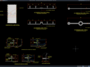
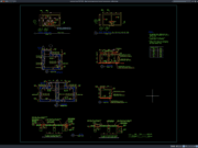
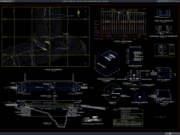
As shown in the drawing, the CAD sheet presents several detailed concrete wall construction joint and expansion joint configurations, including construction joints, expansion joints, waterstop arrangements, waterproofing membranes, protection hardboards, joint fillers, sealants, reinforcement, and shear connector details. The different joint profiles provide practical references for coordinating movement and concrete interfaces within reinforced concrete wall systems.
The upper-left portion of the drawing illustrates a construction joint in a concrete wall, showing the relationship between the concrete wall sections and the joint interface. The detail identifies components such as an internal waterstop, waterproofing membrane, protection hardboard, and concrete joint interface. These components help demonstrate how a wall joint can be coordinated with both structural and waterproofing requirements.
The upper and middle portions contain several construction joint and expansion joint profiles, including different joint configurations identified as Type-1 and Type-2. The details show joint dimensions, centerlines, joint gaps, and specialized joint components. Some of the profiles are identified as Greenstreak or equivalent, providing a reference for proprietary or equivalent joint-forming and waterstop systems.
The drawing also presents expansion joint details for different wall conditions, including expansion joints in varying wall thicknesses and expansion joints between walls with the same thickness. These sections illustrate how the joint interface, waterstop, waterproofing membrane, protection board, sealant, and reinforcement can be coordinated around the concrete wall.
A significant feature of the drawing is the waterproofing and waterstop arrangement. The detailed sections show internal waterstops positioned within the concrete joint together with waterproofing membrane and protective hardboard layers. Proper coordination of these components is particularly important for walls exposed to groundwater, moisture, or hydrostatic pressure, such as basements, retaining structures, underground facilities, and water-retaining structures.
The lower portion also includes a shear connector detail, illustrating how a structural connector can be incorporated at a concrete joint. The detail provides additional information about the relationship between the connector, joint interface, waterproofing, and surrounding reinforced concrete. Such details are useful when structural interaction between adjacent concrete elements must be maintained while accommodating the requirements of the joint.
Accurate joint detailing is essential because improperly designed or installed concrete construction and expansion joints may result in water leakage, uncontrolled cracking, reinforcement conflicts, inadequate movement accommodation, poor joint alignment, or premature deterioration of the concrete structure. Proper coordination between structural design, reinforcement, waterproofing, waterstops, joint fillers, sealants, and construction sequencing can help improve the durability and performance of the completed structure.
Detailed AutoCAD DWG files allow engineers and CAD technicians to review and adapt joint widths, wall thicknesses, reinforcement arrangements, waterstop locations, waterproofing layers, protection boards, joint fillers, sealant details, and shear connector configurations according to specific project requirements and applicable engineering standards.
The drawing shown provides a practical reference for concrete wall construction joints, reinforced concrete expansion joints, waterstop details, waterproofing coordination, joint filler details, shear connector installation, concrete wall reinforcement, movement joint detailing, structural drafting, and construction documentation.
For those of you who prefer a simpler and faster download experience on asdar.id, I also provide a Premium Member Download service that allows direct access to the original file. This way, you will not be disturbed by excessive advertisements or multiple redirect pages during the download process. If you are interested, please register HERE. Please download the Concrete Wall Construction Joint and Expansion Joint Details DWG AutoCAD file below:
Concrete Wall Construction Joint and Expansion Joint Details DWG AutoCAD
| Google Drive | DOWNLOAD[121.73KB] |
| Mediafire | DOWNLOAD[121.73KB] |
Rar password: www.asdar.id
Important Note: If you encounter a problem where the WinRAR file cannot be extracted or appears corrupted, the solution is to update the WinRAR application on your computer to the latest version. Download the latest version of WinRAR here.
If you would like to copy this article, please include the original source because I have seen some blogs repost the content without providing proper credit. Otherwise, please rewrite it using your own words. Respect and appreciate the work and effort of others.
Concrete Wall Construction Joint and Expansion Joint Details DWG AutoCAD provide valuable technical references for understanding the proper coordination of concrete joints, reinforcement, waterstops, waterproofing membranes, joint fillers, sealants, and structural interfaces.
Accurate joint documentation can help structural engineers, civil engineers, architects, contractors, CAD technicians, BIM coordinators, and construction professionals improve communication and coordination throughout the design and construction process.
Whether used for reinforced concrete walls, retaining structures, basements, water-retaining facilities, or other concrete applications, properly detailed construction and expansion joints are essential for managing construction sequences, structural movement, waterproofing requirements, and long-term durability.