





 asdar.id menyediakan Member Premium Download untuk download file tanpa embel-embel iklan dan halaman, apa lagi harus menunggu timer yang begitu lama. Dengan berlangganan Member Premium Download, semua file dapat didownload dengan singkat langsung menuju ke sumbernya!, klik DISINI untuk DAFTAR atau DISINI untuk LOGIN :-) Jika ada pertanyaan silahkan hubungi Admin DISINI. Untuk cara download file Member Free Download, bisa membaca Tutorial Download yang ada dibawah Timer (halaman Safelink) saat menekan tombol download.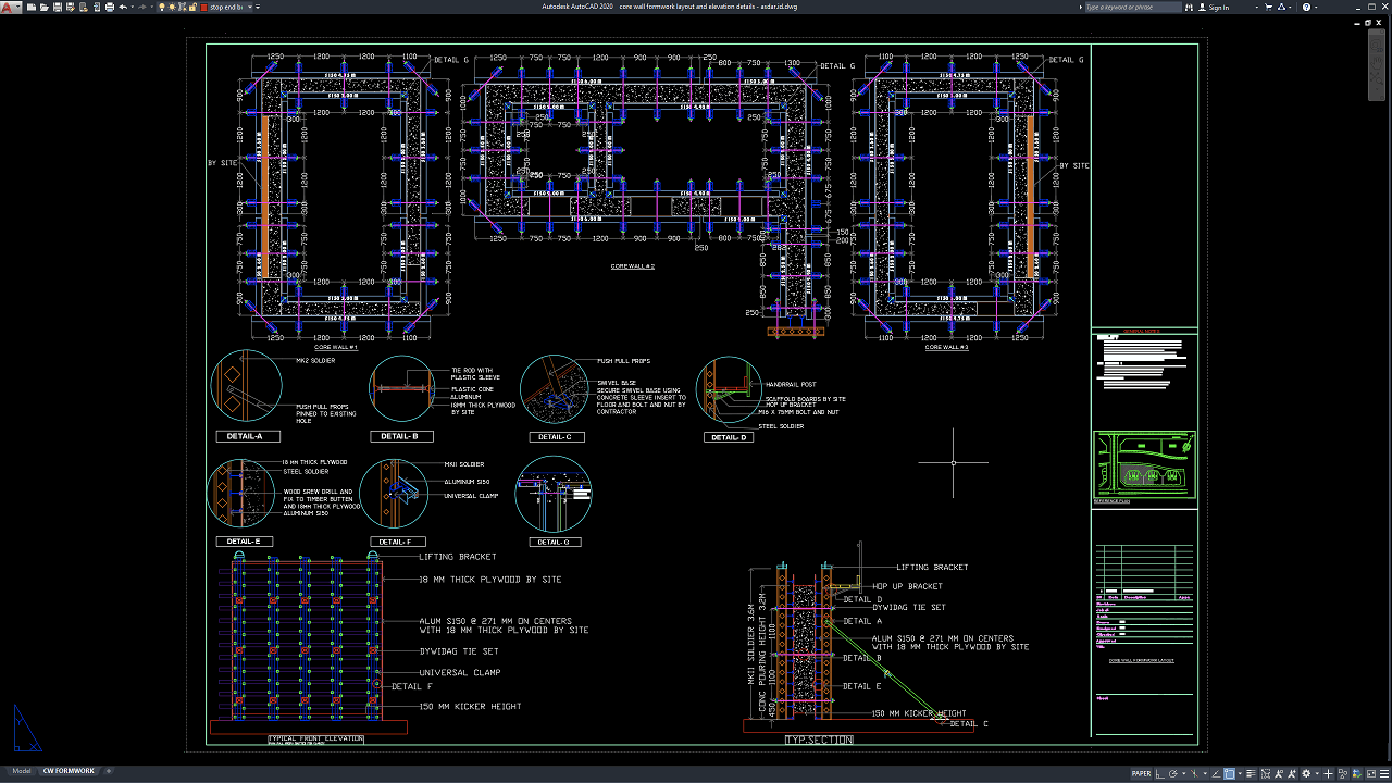
Core Wall Formwork Layout and Elevation Details DWG AutoCAD can be a valuable technical reference for understanding the arrangement, dimensions, elevations, and construction configuration of formwork used for reinforced concrete core walls. Core walls are important structural elements in many multi-story buildings because they can accommodate staircases, elevator shafts, service cores, and contribute to the overall lateral stability of the structure.
Detailed formwork drawings help construction teams understand how temporary molds and supporting components should be arranged before concrete placement. They are particularly useful for structural engineers, civil engineers, architects, contractors, formwork specialists, site engineers, CAD technicians, BIM coordinators, quantity surveyors, and construction professionals.
What Is Core Wall Formwork?
Core wall formwork is a temporary construction system used to create the required shape and dimensions of reinforced concrete core walls. The formwork provides a controlled surface for fresh concrete while it is being placed, compacted, and cured.
In high-rise and multi-story construction, core walls can have complex geometries because they may surround elevator shafts, staircases, mechanical spaces, or other vertical service areas. Proper formwork planning is therefore important for achieving accurate wall dimensions and efficient construction cycles.
Why Core Wall Formwork Details Are Important
Formwork accuracy has a direct relationship with the quality and efficiency of reinforced concrete construction. Incorrect positioning can affect wall dimensions, openings, alignment, concrete cover, construction joints, and connections with adjacent structural elements.
Well-coordinated formwork drawings provide construction teams with a clearer understanding of the temporary works before installation begins. They can also help identify potential clashes between formwork, reinforcement, embedded components, MEP installations, and architectural requirements.
For large construction projects, detailed formwork documentation can also support construction sequencing and improve coordination between the design and site teams.
Download Core Wall Formwork Layout and Elevation Details DWG AutoCAD
Proper Core Wall Formwork Layout and Elevation Details DWG AutoCAD drawings are important technical references for understanding the arrangement, dimensions, elevations, supporting components, and construction details of formwork used for reinforced concrete core walls. These drawings are particularly useful for structural engineers, civil engineers, contractors, formwork specialists, site engineers, CAD technicians, BIM coordinators, and construction professionals involved in reinforced concrete building projects.
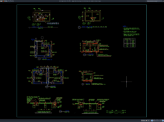
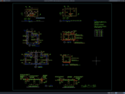
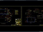
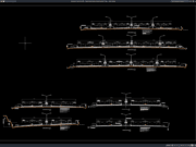
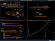
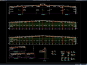
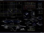
As shown in the drawing, the CAD sheet presents several detailed core wall formwork layouts, including formwork arrangements for Core Wall #1, Core Wall #2, and Core Wall #3. The drawings show the geometry of the core walls, dimensional references, formwork panel positions, support locations, and connections between different formwork components. These layouts provide useful information for understanding how the temporary formwork system is arranged around the concrete core.
The upper portion of the drawing contains multiple core wall formwork layout views with detailed dimensions around the wall perimeter. The layouts illustrate the positions of formwork panels, corner arrangements, internal wall faces, and supporting elements. Dimensional references such as 750 mm, 900 mm, 1200 mm, and other panel-related measurements help define the configuration and spacing of the formwork system.
The drawing also includes several formwork connection and support details, identified as Detail A through Detail G. These details illustrate components such as MK2 Soldier elements, push-pull props, tie rods with plastic sleeves, DYWIDAG tie sets, universal clamps, handrail posts, steel soldiers, and plywood formwork. These components work together to provide stability, alignment, connection, and support during concrete wall construction.
A typical front elevation is provided in the lower portion of the drawing, showing the vertical arrangement of the formwork system. The elevation illustrates the plywood facing, aluminum S150 components, DYWIDAG tie sets, universal clamps, and a 150 mm kicker height. This view helps clarify the vertical positioning and relationship between the individual formwork components.
The drawing also presents a typical section through the core wall formwork. The section illustrates the concrete pouring height, formwork panels, aluminum profiles, plywood facing, tie system, lifting bracket, push-pull components, and other temporary construction elements. This sectional representation is useful for understanding how the formwork is supported and connected around the reinforced concrete core wall.
Additional information is provided for lifting brackets and formwork handling components. These details are important because large core wall formwork panels may need to be positioned, adjusted, and relocated during successive concrete pours. Properly detailed lifting and connection components can help construction teams understand the intended arrangement of the temporary works.
Incomplete or inaccurate Core Wall Formwork Layout and Elevation Details may result in incorrect panel dimensions, poor wall alignment, unstable formwork, connection conflicts, difficulties during concrete placement, or problems when repositioning the formwork system. Proper coordination between structural engineers, formwork specialists, contractors, site engineers, and construction teams is therefore important before formwork installation and concrete works begin.
Detailed AutoCAD DWG files allow engineers, contractors, and CAD technicians to review and adapt core wall formwork layouts, elevations, dimensions, panel arrangements, support components, tie systems, lifting brackets, and connection details according to specific project requirements and applicable construction standards. The drawing shown provides a practical reference for core wall formwork design, concrete wall formwork, formwork layout, formwork elevation, formwork section details, MK2 Soldier system, push-pull props, DYWIDAG tie systems, plywood formwork, aluminum formwork components, lifting brackets, structural drafting, and construction documentation.
For those of you who prefer a simpler and faster download experience on asdar.id, I also provide a Premium Member Download service that allows direct access to the original file. This way, you will not be disturbed by excessive advertisements or multiple redirect pages during the download process. If you are interested, please register HERE. Please download the Core Wall Formwork Layout and Elevation Details DWG AutoCAD file below:
Core Wall Formwork Layout and Elevation Details DWG AutoCAD
| Google Drive | DOWNLOAD[1.57MB] |
| Mediafire | DOWNLOAD[1.57MB] |
Rar password: www.asdar.id
Important Note: If you encounter a problem where the WinRAR file cannot be extracted or appears corrupted, the solution is to update the WinRAR application on your computer to the latest version. Download the latest version of WinRAR here.
If you would like to copy this article, please include the original source because I have seen some blogs repost the content without providing proper credit. Otherwise, please rewrite it using your own words. Respect and appreciate the work and effort of others.
The Core Wall Formwork Layout and Elevation Details DWG AutoCAD provides a useful reference for understanding how core wall formwork can be represented through layout and elevation drawings. These views help clarify the horizontal configuration, vertical arrangement, dimensions, construction levels, and supporting components of temporary formwork systems.
For structural engineers, contractors, site engineers, formwork specialists, CAD technicians, BIM coordinators, and architecture or engineering students, an editable DWG reference can support technical drafting, construction planning, coordination, and formwork studies. Proper professional review remains essential before applying any drawing to an actual construction project.