





 asdar.id menyediakan Member Premium Download untuk download file tanpa embel-embel iklan dan halaman, apa lagi harus menunggu timer yang begitu lama. Dengan berlangganan Member Premium Download, semua file dapat didownload dengan singkat langsung menuju ke sumbernya!, klik DISINI untuk DAFTAR atau DISINI untuk LOGIN :-) Jika ada pertanyaan silahkan hubungi Admin DISINI. Untuk cara download file Member Free Download, bisa membaca Tutorial Download yang ada dibawah Timer (halaman Safelink) saat menekan tombol download.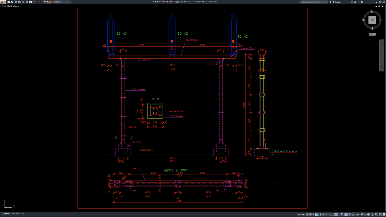
Supporting structures for electrical isolators are important components in high-voltage substations because they provide stable, accurately positioned mounting points for disconnecting equipment and associated electrical components. These structures must safely resist equipment weight, conductor forces, wind loads, seismic effects, operational forces, and other project-specific loads while maintaining the required electrical clearances.
In this article, we share a reference for Supporting Structures for Isolators Details DWG AutoCAD that can be useful for electrical engineers, civil engineers, structural engineers, substation designers, EPC contractors, steel fabricators, CAD technicians, BIM coordinators, quantity surveyors, construction managers, and engineering students.
The drawing can provide a practical reference for substation steel structure design, high-voltage isolator supports, structural engineering services, steel fabrication, foundation coordination, BIM coordination, construction cost estimation, quantity takeoff, and EPC substation construction.
What Are Supporting Structures for Isolators?
Supporting structures for isolators are structural steel or reinforced concrete assemblies designed to support high-voltage electrical isolators, also commonly referred to as disconnect switches or disconnectors, within electrical substations.
The isolator itself must be installed at a precise position and elevation so that it can connect correctly with conductors, busbars, insulators, and other electrical equipment. The supporting structure provides the required height, stability, and structural resistance.
Depending on the substation design, the support may consist of steel columns, cross members, brackets, bracing, base plates, anchor bolts, connection plates, and concrete foundations.
Function of Electrical Isolators
An electrical isolator is primarily used to provide visible electrical isolation between sections of a high-voltage circuit.
Unlike a circuit breaker, an isolator is generally not intended to interrupt significant load or fault current. Its main purpose is to establish a clearly isolated condition so maintenance or inspection can be performed safely after the circuit has been de-energized by the appropriate switching equipment.
Because the isolator operates mechanically, its supporting structure must remain sufficiently rigid to maintain proper equipment alignment throughout repeated operating cycles.
Download Supporting Structures for Isolators Details DWG AutoCAD
Proper Supporting Structures for Isolators Details DWG AutoCAD drawings are essential for accurately coordinating steel support columns, horizontal cross members, isolator mounting points, equipment loads, base connections, foundations, and overall structural dimensions within high-voltage substation projects. Structural engineers, electrical engineers, civil engineers, EPC contractors, steel fabricators, equipment installers, and site teams must carefully coordinate support elevations, member spacing, isolator positions, foundation locations, and connection details to achieve a stable, accurately aligned, and constructible support structure.
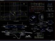
Detailed drawings such as isolator support elevations, steel column details, cross-member layouts, top views, equipment mounting positions, foundation details, base connections, and dimensional references help engineering and fabrication teams understand the complete structural arrangement before steel fabrication and electrical equipment installation begin. As shown in the drawing, the structure supports three isolators, each indicated with a load of approximately 90 kg, mounted along a horizontal steel cross member with an overall length of approximately 4200 mm. The system is supported by two vertical steel columns spaced approximately 3200 mm apart, with a total structural height shown at approximately 3282 mm, together with Foundation F-1, base details, and a dedicated top view illustrating the member and mounting arrangement.
Incomplete or inaccurate Supporting Structures for Isolators Details may result in incorrect isolator spacing, unsuitable equipment elevations, excessive structural movement, misaligned mounting points, foundation positioning errors, and difficulties connecting isolators with adjacent conductors or substation equipment. Accurate structural drawings and proper coordination between electrical engineers, structural engineers, civil engineers, steel fabricators, EPC contractors, equipment suppliers, surveyors, and site installation teams are therefore important for achieving reliable and properly aligned high-voltage equipment supports.
Detailed AutoCAD DWG files also allow engineers and fabricators to review and modify steel column heights, cross-member lengths, isolator positions, support spacing, base connections, foundation interfaces, and other dimensional details according to specific equipment requirements and applicable structural standards. The drawing shown provides a practical reference for high-voltage isolator support design, substation steel structures, equipment mounting coordination, steel fabrication detailing, foundation coordination, and electrical infrastructure construction documentation.
For those of you who prefer a simpler and faster download experience on asdar.id, I also provide a Premium Member Download service that allows direct access to the original file. This way, you will not be disturbed by excessive advertisements or multiple redirect pages during the download process. If you are interested, please register HERE. Please download the Supporting Structures for Isolators Details DWG AutoCAD file below:
Supporting Structures for Isolators Details DWG AutoCAD
| Google Drive | DOWNLOAD[454.87KB] |
| Mediafire | DOWNLOAD[454.87KB] |
Rar password: www.asdar.id
Important Note: If you encounter a problem where the WinRAR file cannot be extracted or appears corrupted, the solution is to update the WinRAR application on your computer to the latest version. Download the latest version of WinRAR here.
If you would like to copy this article, please include the original source because I have seen some blogs repost the content without providing proper credit. Otherwise, please rewrite it using your own words. Respect and appreciate the work and effort of others.
Supporting Structures for Isolators Details DWG AutoCAD drawings provide valuable technical references for understanding how high-voltage electrical isolators are supported by structural steel frames, bracing, mounting components, base plates, anchor bolts, and reinforced concrete foundations.
Accurate structural documentation improves coordination between electrical engineers, structural engineers, civil engineers, equipment manufacturers, steel fabricators, EPC contractors, quantity surveyors, and construction teams. It can also support better substation design, BIM coordination, steel fabrication, quantity takeoff, construction cost estimation, procurement planning, erection scheduling, and long-term maintenance of electrical infrastructure.