





 asdar.id menyediakan Member Premium Download untuk download file tanpa embel-embel iklan dan halaman, apa lagi harus menunggu timer yang begitu lama. Dengan berlangganan Member Premium Download, semua file dapat didownload dengan singkat langsung menuju ke sumbernya!, klik DISINI untuk DAFTAR atau DISINI untuk LOGIN :-) Jika ada pertanyaan silahkan hubungi Admin DISINI. Untuk cara download file Member Free Download, bisa membaca Tutorial Download yang ada dibawah Timer (halaman Safelink) saat menekan tombol download.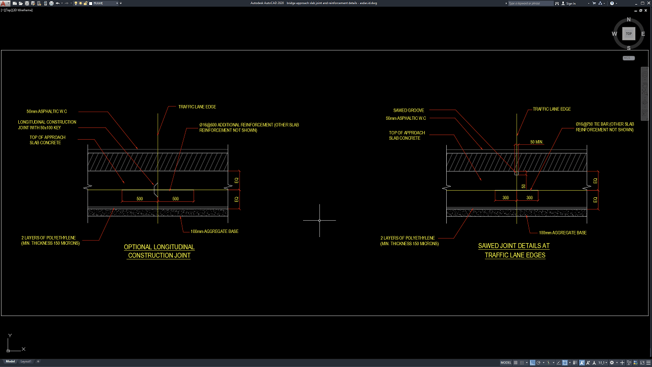
Bridge Approach Slab Joint and Reinforcement Details DWG AutoCAD drawings provide a useful technical reference for understanding the structural arrangement, reinforcement configuration, and connection details of a bridge approach slab. These drawings are valuable for civil engineers, bridge engineers, structural engineers, CAD technicians, BIM modelers, contractors, consultants, quantity surveyors, and civil engineering students who need references for bridge design and construction documentation.
A bridge approach slab is an important transition element between the bridge structure and the adjoining roadway. It helps provide a smoother transition for vehicles, accommodates the structural relationship between the bridge and road embankment, and reduces the effects of differential settlement when properly designed. Joint details and reinforcement arrangements are therefore important considerations in bridge construction.
What Is a Bridge Approach Slab?
A bridge approach slab is a reinforced concrete slab constructed at the approach to a bridge, generally between the bridge abutment and the adjacent roadway. Its primary purpose is to provide a relatively smooth transition between the bridge deck and the road pavement.
The approach slab is designed to accommodate the expected loading conditions and the interaction between the bridge structure and the supporting ground. Its dimensions, thickness, reinforcement, support conditions, and connection details depend on the bridge design, geotechnical conditions, traffic loading, and applicable engineering standards.
Bridge approach slab joint details describe the connection or separation arrangement between the approach slab and adjacent structural or pavement elements. Depending on the design, these details may include expansion joints, construction joints, dowels, connection bars, bearing or support interfaces, and other components required to accommodate movement or transfer forces.
Meanwhile, reinforcement details illustrate the arrangement of reinforcing steel within the concrete slab. These details may include longitudinal and transverse reinforcement, bar spacing, concrete cover, anchorage lengths, lap splices, and reinforcement continuity near joints.
Functions of Bridge Approach Slab Joints and Reinforcement
Bridge approach slab joints and reinforcement perform important roles in the durability, serviceability, and structural performance of a bridge approach system.
1. Providing a Smooth Transition
The approach slab helps connect the bridge deck to the adjacent roadway. Proper design can reduce abrupt changes in the road surface and improve vehicle comfort when crossing the bridge approach.
2. Accommodating Structural Movement
Joint details may accommodate relative movement caused by temperature changes, shrinkage, settlement, and other design considerations. The joint configuration must be coordinated with the movement requirements of the bridge and approach slab.
3. Distributing Traffic Loads
Reinforcement helps the concrete slab resist tensile stresses and control cracking under the loads considered in the structural design. The reinforcement arrangement must be determined through appropriate engineering calculations.
4. Improving Structural Durability
Proper reinforcement detailing, concrete cover, joint configuration, and drainage coordination can help reduce the risk of premature deterioration. These considerations are particularly important in bridge environments exposed to moisture, weather, deicing chemicals where applicable, and repeated traffic loading.
5. Supporting Construction Accuracy
Clear joint and reinforcement drawings help contractors and reinforcement installers understand bar positions, spacing, anchorage, and connection requirements. This information can reduce misunderstandings during construction and improve coordination between the design and site teams.
Download Bridge Approach Slab Joint and Reinforcement Details DWG AutoCAD
Proper Bridge Approach Slab Joint and Reinforcement Details DWG AutoCAD drawings are useful technical references for understanding the joint configuration, reinforcement arrangement, concrete slab layers, and connection details of a bridge approach slab. These drawings are particularly useful for civil engineers, bridge engineers, structural engineers, contractors, CAD technicians, reinforcement detailers, and construction professionals involved in bridge design and infrastructure projects.
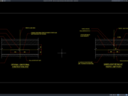
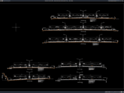
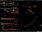
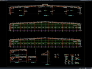
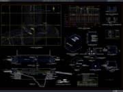
As shown in the drawing, the CAD detail presents sectional views of bridge approach slab joints, focusing on the connection between the concrete slab, asphalt pavement, reinforcement bars, and underlying aggregate base. Two joint configurations are illustrated: an optional longitudinal construction joint and sawed joint details at traffic lane edges. Technical annotations identify the relevant construction components, reinforcement positions, and dimensions.
The left detail illustrates an optional longitudinal construction joint between adjacent portions of the approach slab. The drawing identifies a longitudinal construction joint with a 50 × 100 key, the top of the approach slab concrete, additional reinforcement, a 50 mm asphaltic wearing course, two layers of polyethylene sheeting, and a 100 mm aggregate base. These components provide a useful reference for understanding the interface between the concrete slab sections and the pavement layers.
The right detail shows sawed joint details at traffic lane edges, including the sawed groove, asphaltic wearing course, approach slab concrete, transverse reinforcement, polyethylene layers, and aggregate base. Dimensions and annotations indicate the intended joint geometry and the relationship between the joint location and the reinforcing bars. These details help clarify how the joint is represented within the overall slab section.
The sectional representations allow engineers and contractors to examine the relationship between concrete slab joints, reinforcing steel, pavement layers, and the supporting base. Correct coordination of these elements is important for construction accuracy, crack control, pavement performance, and the long-term serviceability of bridge approach areas. The specified joint configuration and reinforcement must be verified against the applicable structural design and project requirements.
Incomplete or inaccurate Bridge Approach Slab Joint and Reinforcement Details may result in incorrect joint dimensions, misplaced reinforcement, insufficient concrete cover, construction conflicts, or difficulties during concrete placement. Poor coordination between the slab, pavement, and supporting layers may also contribute to cracking, water infiltration, and premature deterioration. Proper review by structural engineers, bridge engineers, contractors, and site personnel is therefore essential before construction.
Detailed AutoCAD DWG files allow engineers and CAD technicians to review and adapt the joint geometry, reinforcement arrangement, slab dimensions, pavement layers, and construction annotations according to project-specific requirements. The drawing shown provides a practical reference for bridge approach slab joint details, concrete reinforcement detailing, longitudinal construction joints, sawed joint details, bridge pavement sections, rebar arrangement, reinforced concrete drawings, bridge construction details, structural CAD drafting, and civil engineering documentation.
For those of you who prefer a simpler and faster download experience on asdar.id, I also provide a Premium Member Download service that allows direct access to the original file. This way, you will not be disturbed by excessive advertisements or multiple redirect pages during the download process. If you are interested, please register HERE. Please download the Bridge Approach Slab Joint and Reinforcement Details DWG AutoCAD file below:
Bridge Approach Slab Joint and Reinforcement Details DWG AutoCAD
| Google Drive | DOWNLOAD[58.65KB] |
| Mediafire | DOWNLOAD[58.65KB] |
Rar password: www.asdar.id
Important Note: If you encounter a problem where the WinRAR file cannot be extracted or appears corrupted, the solution is to update the WinRAR application on your computer to the latest version. Download the latest version of WinRAR here.
If you would like to copy this article, please include the original source because I have seen some blogs repost the content without providing proper credit. Otherwise, please rewrite it using your own words. Respect and appreciate the work and effort of others.
The Bridge Approach Slab Joint and Reinforcement Details DWG AutoCAD provides a useful technical reference for understanding the joint configuration, reinforcement arrangement, and structural relationship between a bridge approach slab and adjacent bridge or roadway elements.
For civil engineers, bridge engineers, structural engineers, contractors, CAD technicians, and engineering students, these drawings can support structural detailing, design coordination, construction planning, and technical studies. However, a reference drawing should not replace project-specific engineering design. All joint dimensions, reinforcement specifications, movement requirements, and construction details must be verified by qualified professionals before being used in an actual bridge project.