





 asdar.id menyediakan Member Premium Download untuk download file tanpa embel-embel iklan dan halaman, apa lagi harus menunggu timer yang begitu lama. Dengan berlangganan Member Premium Download, semua file dapat didownload dengan singkat langsung menuju ke sumbernya!, klik DISINI untuk DAFTAR atau DISINI untuk LOGIN :-) Jika ada pertanyaan silahkan hubungi Admin DISINI. Untuk cara download file Member Free Download, bisa membaca Tutorial Download yang ada dibawah Timer (halaman Safelink) saat menekan tombol download.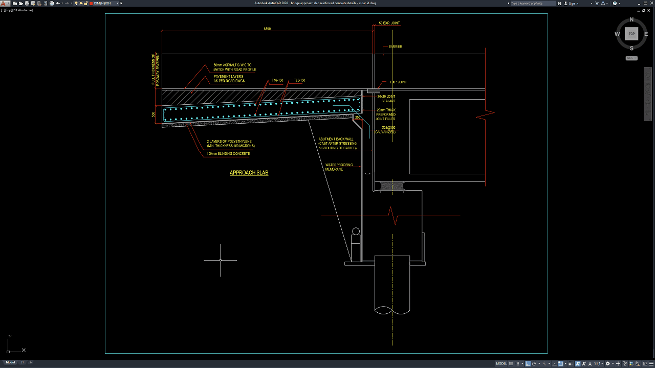
A bridge approach slab is an important transition element between a bridge structure and the adjacent roadway. It helps provide a smoother connection between the relatively rigid bridge deck and the approach embankment while accommodating changes in elevation, settlement, and movement. Proper reinforced concrete detailing is therefore important for maintaining the performance and durability of the transition area.
In this article, we share a reference for Bridge Approach Slab Reinforced Concrete Details DWG AutoCAD that can be useful for civil engineers, structural engineers, bridge designers, contractors, quantity surveyors, rebar detailers, CAD technicians, BIM coordinators, construction managers, and engineering students.
The CAD reference can provide practical information related to approach slab geometry, reinforced concrete construction, reinforcement arrangements, slab sections, bridge connections, roadway interfaces, dimensions, and construction detailing. The editable DWG format can be reviewed and adapted for preliminary studies, structural drafting, quantity takeoff, and construction documentation according to specific project requirements.
What Is a Bridge Approach Slab?
A bridge approach slab is a reinforced concrete slab constructed between the bridge structure and the adjacent roadway or approach embankment. Its main purpose is to provide a structural transition between the bridge deck and the roadway.
Approach slabs are commonly used to reduce the effects of differential settlement and changes in stiffness between the bridge and the surrounding road embankment. Without an appropriate transition system, settlement or movement at the bridge approach can contribute to an uneven roadway surface.
Depending on the project, an approach slab may be connected to the bridge abutment and supported partly by the surrounding fill or foundation system. Its dimensions, reinforcement, thickness, support conditions, and connection details vary according to the bridge design and applicable engineering requirements.
Importance of Bridge Approach Slab Reinforced Concrete Details
Accurate Bridge Approach Slab Reinforced Concrete Details DWG AutoCAD drawings help engineers and construction teams understand the geometry and reinforcement arrangement of the approach slab.
Detailed drawings can illustrate slab thickness, longitudinal reinforcement, transverse reinforcement, concrete dimensions, support conditions, construction joints, connection points, roadway interfaces, and other structural components.
Proper detailing is important because the approach slab is exposed to repeated traffic loading and may be affected by settlement, temperature changes, moisture, and movement at the bridge interface.
Clear technical drawings also improve communication between structural engineers, bridge designers, contractors, reinforcement detailers, surveyors, and site personnel during construction.
Download Bridge Approach Slab Reinforced Concrete Details DWG AutoCAD
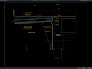
Proper Bridge Approach Slab Reinforced Concrete Details DWG AutoCAD drawings are important technical references for understanding the dimensions, reinforcement, construction layers, expansion joints, waterproofing, and structural connection between a bridge approach slab and the abutment. These drawings are particularly useful for civil engineers, structural engineers, bridge designers, contractors, rebar detailers, CAD technicians, quantity surveyors, and construction professionals involved in bridge and roadway infrastructure design.
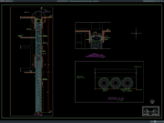
As shown in the drawing, the CAD detail presents a typical reinforced concrete bridge approach slab connecting the roadway pavement to the bridge abutment. The drawing identifies the approach slab, roadway pavement layers, reinforcement, expansion joint, joint sealant, joint filler, waterproofing membrane, polyethylene layers, blinding concrete, and abutment back wall. These components illustrate how the approach transition is constructed and coordinated with the supporting bridge structure.
The upper portion of the drawing shows the approach slab extending from the roadway toward the bridge abutment, with an indicated overall length of approximately 6500 mm. The slab is positioned beneath the roadway pavement layers and includes reinforcement references such as T16-150 and T20-150. These reinforcement callouts provide information about the arrangement and spacing of reinforcing bars within the concrete approach slab.
At the bridge interface, the drawing identifies a 50 mm expansion joint, 20 × 20 mm joint sealant, and 20 mm thick preformed joint filler. These components provide a controlled separation between the approach slab and the adjacent bridge structure. The detail also shows a barrier and the relationship between the expansion joint and the roadway pavement profile.
The drawing further illustrates the layers beneath the approach slab, including two layers of polyethylene, 100 mm blinding concrete, and a waterproofing membrane around the abutment area. These construction layers help demonstrate how the approach slab and bridge abutment interface can be coordinated with moisture protection and supporting elements.
The abutment back wall is also shown beneath the approach slab, together with the supporting foundation arrangement. This section provides a useful reference for understanding the transition between the reinforced concrete approach slab, bridge abutment, roadway pavement, and foundation system.
Incomplete or inaccurate Bridge Approach Slab Reinforced Concrete Details may result in incorrect reinforcement placement, unsuitable expansion joint arrangements, inadequate waterproofing, pavement transition problems, construction conflicts, or difficulties during installation. Proper coordination of the approach slab, reinforcement, pavement layers, joint components, waterproofing membrane, abutment, and foundation is therefore important for developing a reliable bridge-to-roadway transition.
Detailed AutoCAD DWG files allow engineers and CAD technicians to review and adapt approach slab dimensions, reinforcement spacing, pavement layers, expansion joint details, joint sealant, waterproofing components, blinding concrete, and abutment connections according to specific project requirements and applicable engineering standards. The drawing shown provides a practical reference for bridge approach slab detailing, reinforced concrete approach slabs, approach slab reinforcement, bridge expansion joints, roadway pavement connections, abutment interface details, waterproofing, construction joint detailing, structural drafting, and bridge construction documentation.
For those of you who prefer a simpler and faster download experience on asdar.id, I also provide a Premium Member Download service that allows direct access to the original file. This way, you will not be disturbed by excessive advertisements or multiple redirect pages during the download process. If you are interested, please register HERE. Please download the Bridge Approach Slab Reinforced Concrete Details DWG AutoCAD file below:
Bridge Approach Slab Reinforced Concrete Details DWG AutoCAD
| Google Drive | DOWNLOAD[58.62KB] |
| Mediafire | DOWNLOAD[58.62KB] |
Rar password: www.asdar.id
Important Note: If you encounter a problem where the WinRAR file cannot be extracted or appears corrupted, the solution is to update the WinRAR application on your computer to the latest version. Download the latest version of WinRAR here.
If you would like to copy this article, please include the original source because I have seen some blogs repost the content without providing proper credit. Otherwise, please rewrite it using your own words. Respect and appreciate the work and effort of others.
Bridge Approach Slab Reinforced Concrete Details DWG AutoCAD provides a practical technical reference for studying the geometry, reinforcement, sections, connections, and construction interfaces of reinforced concrete bridge approach slabs.
These drawings can support bridge structural design, reinforced concrete detailing, reinforcement planning, quantity takeoff, construction cost estimation, BIM coordination, roadway transition design, bridge rehabilitation, CAD drafting, and construction documentation.
A bridge approach slab should be considered as part of the complete bridge and roadway transition system. Reinforcement, slab dimensions, bridge connections, settlement conditions, drainage, waterproofing, pavement interfaces, construction joints, and structural movement all need to be properly coordinated.
The DWG AutoCAD format provides flexibility for reviewing and adapting technical drawing information, but a generic CAD reference should not replace project-specific engineering design. Actual construction drawings should be checked and approved by qualified professionals based on the applicable bridge design standards, structural calculations, site conditions, material specifications, and project requirements.